My M3 (or Jazper's M3 Monster)
Jul 11, 2005 at 5:01 AM Post #61 of 73
500 mA class A for a headphone amp seems to be much. Have you measured anything like with Rightmark Audio Analyzer? Maybe you are getting side effects if the design wasn't made for that much bias?

If you use +- 13.5 volts I think you are ruin a bit the "soul" of the amp. The soul was to have a ground channel which means that you use a single voltage.
 
Jul 11, 2005 at 5:11 AM Post #62 of 73
Quote:

Originally Posted by peranders
500 mA class A for a headphone amp seems to be much. Have you measured anything like with Rightmark Audio Analyzer? Maybe you are getting side effects if the design wasn't made for that much bias?

If you use +- 13.5 volts I think you are ruin a bit the "soul" of the amp. The soul was to have a ground channel which means that you use a single voltage.


current draw for the M³ would be approx:

140mA per mosfet pair (420mA) (quiescent)

+opamps (7mA each - opa637/627 combo) (21mA)

+ LED (10mA)

+ various transistor stages (say 15mA )

Quick maths tells me thats approx 466mA

I haven't used rightmark (I don't have a the hardware to measure it) but on amb's site he mentions you can increase the quiescent current and quite a few people have reported better bass response from it. The mosfets are running about 45C (ambient 25~ C ) so it's not cooking them.

Quote:

Originally Posted by amb

So, for a 32 ohm load, if we want to achieve, say, 6Vp-p (3V average) without dropping out of class A, then that's 3V / 32 ohms = 94mA. One half of that is ~50mA. Give it a healthy bit of extra margin and let's say we run at 80mA, with +/-12V rails, then each output MOSFET will dissipate 12V * 0.08A = ~1W. This is for the left and right channels. Since the ground channel has to potentially sink or source twice the current return (such as in the case of a mono signal), then the ground channel should be biased to twice that amount. If you want to get even higher output swings into 32 ohm load or if you want to run even lower load impedances with the same voltage swing, then the quiescent current must be increased or you drop out of class A at high volumes.


(I'm using ms-1s - 32 ohm headphones)
 
Jul 11, 2005 at 5:25 AM Post #63 of 73
Quote:

Originally Posted by Jazper
...
(I'm using ms-1s - 32 ohm headphones)


But do realize that when I mentioned 6Vp-p output, that is going to be insanely loud in your headphones (in fact, it may be enough to damage it). Under normal listening conditions you will not get anywhere close to that much voltage swing with low impedance cans. So, even the "standard" 80mA quiescent has plenty of margin. Only when you use something low impedance and ridiculously inefficient would you ever drop out of class A.
 
Jul 11, 2005 at 5:27 AM Post #64 of 73
Quote:

Originally Posted by amb
But do realize that when I mentioned 6Vp-p output, that is going to be insanely loud in your headphones (in fact, it may be enough to damage it). Under normal listening conditions you will not get anywhere close to that much voltage swing with low impedance cans. So, even the "standard" 80mA quiescent has plenty of margin. Only when you use something low impedance and ridiculously inefficient would you ever drop out of class A.


good point, I'll turn them down a bit. (turned down to 110mA - which would make the amp draw 90ma less .. 380 mA or so I'm guessing.. )
 
Jul 12, 2005 at 8:08 AM Post #65 of 73
I have just tested my Super Regulator with 25.30 V as output.

Used parts, exactly as the basic design with the following changes:

T4 D44H11
T1, T6 BC560C
IC2 LM329 (6.830 V)
R3 2k2
R8 2k7


Load, current, min voltage in
40 ohms, 625mA, 28.48V min
30 ohms, 833mA, 28.80V min
20 ohms, 1250mA, 29.42V min

Note that min voltage in is really min voltage so if you have ripple you must add it. If you don't are able to verify how much ripple you have got you must have some safety margin.

The regulator is not otimized for more than 15-18 volts out so if you really want it to work good at more than 24 V out every single part must be examined.

If you use the regulator with a preregulator you will only have 2-2.5 volts voltage drop over the main regulator, this may cause you trouble if you don't know the design.
 
Jul 12, 2005 at 8:16 AM Post #66 of 73
Quote:

Originally Posted by peranders
I have just tested my Super Regulator with 25.30 V as output.

Used parts, exactly as the basic design with the following changes:

T4 D44H11
T1, T6 BC560C
IC2 LM329 (6.830 V)
R3 2k2
R8 2k7


Load, current, min voltage in
40 ohms, 625mA, 28.48V min
30 ohms, 833mA, 28.80V min
20 ohms, 1250mA, 29.42V min

Note that min voltage in is really min voltage so if you have ripple you must add it. If you don't are able to verify how much ripple you have got you must have some safety margin.

The regulator is not otimized for more than 15-18 volts out so if you really want it to work good at more than 24 V out every single part must be examined.

If you use the regulator with a preregulator you will only have 2-2.5 volts voltage drop over the main regulator, this may cause you trouble if you don't know the design.


Right, well if I'm going to do that, then I'm going to need another board, which I can't really afford right at this moment (it's costing me a lot to put this together, and my poor bank account is feeling the hurt) so it's going to have to wait for a little while.
 
Sep 13, 2005 at 1:33 PM Post #68 of 73
I was waiting on the case before I updated this thread, there has been setback after setback with that but finally I think it's going to be ready soon. A few things have happened since I last checked in.

First:
Quote:

Originally Posted by peranders
Since you for a while at least (still I'll hope) has got your Super Regulator working, what's your impressions so far?


Right.. The super regulator is still working so far, I found that the ths4601 opamp seems to be an improvement noise wise for the amp over the ad825. I also tried swapping in the ad797 but it didn't like the capacitive load even with a pair of diodes on the inputs.

I have a ferrite bead over the power cables going out of the jung regulator, to the m3, and have increased capacitance after the regulator (so there's 3000uF straight after the jung, and 3000uF on the amp board) this seems to have helped everything, however bass slam is still marginally less than with the other "cheaper" power supply.

There is still some hiss at high volume which could be source related. I haven't had a whole lot of time to play with different sources yet.

The output wires from the jung are very very sensitive to RF (especially AC hum), I might have to shield the AC wires.

The heatsinks on the jung regulator get pretty hot but the devices are within spec.


Second:
I've removed the C2 capacitors on the m3, and stuck with the ths4631 opamp. Removing the capacitors has seemed to make a very large difference in soundstage, vastly opening it up. Detail has also improved with the ths chips which before seemed very compressed and a bit grainy - while this could be due to burn in, I think it's more an effect of the caps.


I've biased the mosfets to 125mA and am running 25v through the m3. While I have been tempted to increase this I haven't needed to so there hasn't been any motivation to do so. If it ain't broke, don't fix it.

I've found a slight anomaly with the AD8610 opamps, when driven hard (over half volume/gain 11) the treble becomes uncontrolled and peaky, but lower down it is fine. Covenant found the same problem with his mint (ad8620) so I'm guessing it is something to do with having them buffered or perhaps class A bias.

The case for the M3 is due tomorrow night.. I'm going to burn the midnight oil to try and get the amp ready for the meet in sydney on the weekend. Case pictures and final pictures will be forthcoming...

Dakiller heard the amp on the weekend and his first remark was "very very detailed" - so I must have done something right. I've compared to his ppa (which also uses a protoboarded jung and has opa627 opamps) and I prefer the M3 by a large margin.

I have another transformer coming from digikey, one that isn't so big, but I doubt it will be here in time for the meet.


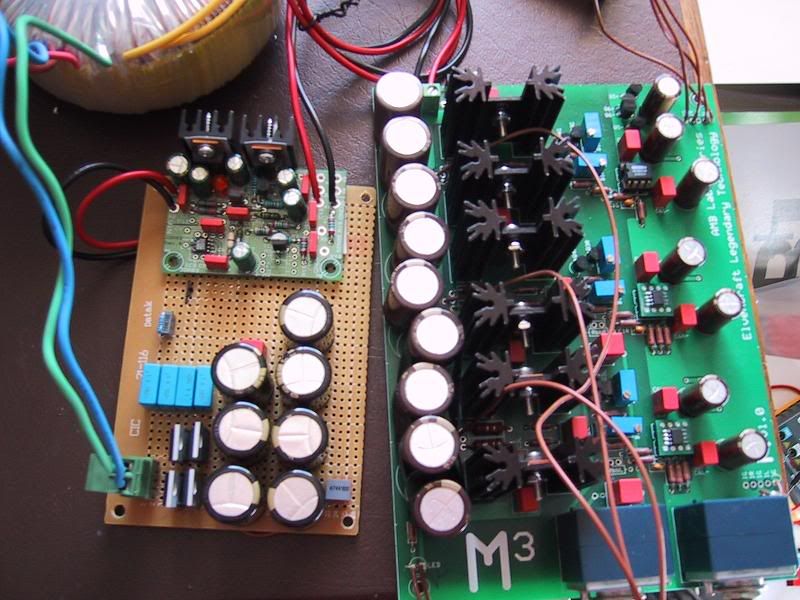
that is all for now... here's a pic of the amp as it is, with the exception that the opamps have been changed to the ths4631s, and the opamp on the jung is now a ths4601:

IMG_0591.jpg


Jaz out (note more up to date pictures are coming..)
 
Sep 13, 2005 at 2:32 PM Post #69 of 73
I think quite many of your problems are related to how you have built and also tested the M3. The M3 has a "virtual ground" and might be sensistive against bad wiring.

It is also recommend NOT to have those huge caps together with a super regulator. The regulator is a wideband device and should not work together with thousand of uF.
 
Sep 14, 2005 at 12:32 AM Post #70 of 73
Quote:

Originally Posted by peranders
It is also recommend NOT to have those huge caps together with a super regulator. The regulator is a wideband device and should not work together with thousand of uF.


There is very little difference in sound except slightly more bass slam, I don't see any reason not to
 
Sep 14, 2005 at 5:03 AM Post #71 of 73
Quote:

Originally Posted by Jazper
...I don't see any reason not to


The reason to use a super regulator is that you want a low noise, low output impedance and most important for you a high speed regulator. If you add too much capacitance you will get worse step response and possible also stablity problems. It's not enough only to have "bass slam" as the only parameter.
 
Sep 14, 2005 at 5:06 AM Post #72 of 73
Quote:

Originally Posted by peranders
The reason to use a super regulator is that you want a low noise, low output impedance and most important for you a high speed regulator. If you add too much capacitance you will get worse step response and possible also stablity problems. It's not enough only to have "bass slam" as the only parameter.


Remember also that with an amplifier you want very quick on demand power. Voltage stability has been fine so far. Within 5mV on average. Further, the caps I'm using are premium, low esr caps anyhow
 

Users who are viewing this thread

Back
Top