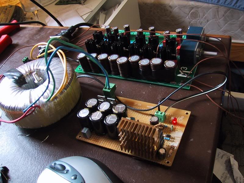
My M3 (or Jazper's M3 Monster)
Jun 25, 2005 at 6:06 AM Post #46 of 73
Quote:

Originally Posted by Jazper
will check after lunch, but I'm pretty sure it's 34.2v

I'm looking for only 28v out..


If you don't have an oscilloscope you must be on the safe side and if you have DC you must have 5 volts at least and if you include ripple you must have up to 10 volts if you also include variations on the mains voltage. Still WHY do you have more than 24 volts? In theory you will get 1 dB more out which you don't hear.
 
Jun 25, 2005 at 6:08 AM Post #47 of 73
Quote:

Originally Posted by peranders
If you don't have an oscilloscope you must be on the safe side and if you have DC you must have 5 volts at least and if you include ripple you must have up to 10 volts if you also include variations on the mains voltage. Still WHY do you have more than 24 volts? In theory you will get 1 dB more out which you don't hear.


I'm not trying to get 1db more, I'm trying to set it up so I have no problem driving high impendance phones, as well as being able to drive low impendance phones.

regardless.. I'll run the numbers for the resistors for 24v..
 
Jun 25, 2005 at 6:18 AM Post #48 of 73
Quote:

Originally Posted by Jazper
Dakiller warned me that it'd cost a lot to get a board from him, but I persisted, I like P-A's designs.


All pcb's goes with a reasonable amount of support so if a board goes for 5-7 USD plus support plus all development time, how much is left? Therefore it must cost a bit more.
 
Jun 25, 2005 at 6:19 AM Post #49 of 73
Quote:

Originally Posted by peranders
All pcb's goes with a reasonable amount of support so if a board goes for 5-7 USD plus support plus all development time, how much is left? Therefore it must cost a bit more.


good call
 
Jun 25, 2005 at 6:24 AM Post #50 of 73
Quote:

Originally Posted by Jazper
I'm not trying to get 1db more, I'm trying to set it up so I have no problem driving high impendance phones, as well as being able to drive low impendance phones.


Still, it's only about dB's. Have you asked the M3 team about this? You don't seem to see the design problem here?

1 Do you need 10-11 V peak to reach desired volume WITH used headphones?

2 Is the volume not enough with 10-11 V so you'll need 12-13 V? => 1 dB more?

You must always think in dB's when it comes to headroom calculations.
 
Jun 25, 2005 at 6:42 AM Post #51 of 73
ok.. I've got resistors to take it to 25.77 (but nothing closer that will keep R7 at 500ish and the voltage at 24ish
 
Jun 25, 2005 at 6:57 AM Post #53 of 73
sorry PA, I don't follow, I said the resistors I have to change R8 and R9 (on JSR03) are
approximately 1800 and 680 ohms. you suggested changing the voltage to 24v, that's the closest I have on hand.

right now I'm disregarding the fact I'd prefer to run a bit higher voltage.
 
Jun 25, 2005 at 7:12 AM Post #54 of 73
Quote:

Originally Posted by Jazper
sorry PA, I don't follow, I said the resistors I have to change R8 and R9 (on JSR03) are
approximately 1800 and 680 ohms. you suggested changing the voltage to 24v, that's the closest I have on hand.

right now I'm disregarding the fact I'd prefer to run a bit higher voltage.


changed to 25.7 - unloaded..
with load.. 23

same as before
 
Jun 27, 2005 at 10:29 AM Post #55 of 73
IT'S ALIVE!!!

changed the toroidal for a much bigger one (20->160VA should be noted that I went 160 because the next step up (80) was only $5 less than the 160, and the dimensions were very similar) and ... wow...

with the little listening I've done so far, I have to say the ad8610s do a better job in this amp than the opa637s for all together listening pleasure, however the 637's do a better job of classical.

will post more when I have it (the amp currently looks the same as the pic above, but a case is coming..
 
Jul 2, 2005 at 1:43 AM Post #57 of 73
After continued frustrations and slip ups (which peranders, and myself attribute to eagerness and shakey hands
rolleyes.gif
) that caused no end of pain troubleshooting the JSR03, I've moved to a derivative of the first power supply that I built based on the diyaudio design, I've used silmic and panasonic caps throughout (for electrolytic), bypassed with polypropylene on the smoothing/holdup caps.


Changes to the original design(note I'm only using half of it):
(original design here: http://www.diyaudio.com/forums/show...&threadid=56106 )

B1 is RHRP860 (made by harris)
Removed R1
C1 is 7000uF (panasonic 1000uF/50v FM caps)
C3 is a no brand polyester cap
C5 is 100uF (rather than 47uF) panasonic 100uF/50v FM
R7 is 27ohm (I think the original value may have been a mistake.. )
C9 is 47uF/35v silmic II
R3 is 47R
R5 is 1k
used LM317T rather than 338 - will be switching on/off from the mains

added:
.1 uF (100nF) vishay polypropylene cap to bypass the power caps
added 10k resistor + red LED on the output so I could tell when it's on and so that there is always some load on it to drain the caps on poweroff.

Notes:
R5 gets pretty warm (I'm running 1/2w resistors, but they're the size of 1/4w resistors, I may change it for 2w when I get the chance)

Vout is approx 26.7v

Sonically, I can't hear the difference between it and the jung(aside the fact that the amp sounds a touch punchier now-which is a good thing), so I must be doing something right or my ears just aren't tuned enough.

One note with the M3 is that it seems to sound much better after it's been warmed up for an hour before listening, before that it seems a bit slower.

Will post pics when I can, but this design is much simpler than the JSR and I'm much more comfortable with it.
 
Jul 4, 2005 at 3:39 AM Post #58 of 73
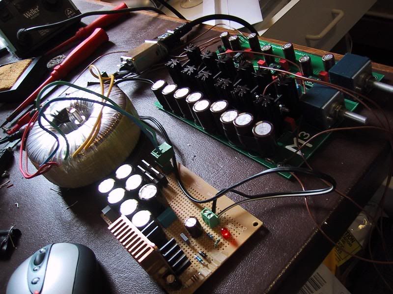
(action shots- ignore mess in the surrounding area.. )

IMG_0583.jpg


IMG_0579.jpg


case is still on its way...(and yes that is an LM317 under all those heatsinks :p )
 
Jul 10, 2005 at 8:01 PM Post #59 of 73
Quote:

Originally Posted by Jazper
Will post pics when I can, but this design is much simpler than the JSR and I'm much more comfortable with it.


It's a pity that you failed here but when I'll got the time later on I'll check especially on a 24-30 volt version. I can't really explain what troubles you did experience. To be really sure that everything is working alright you'll need at least an oscilloscope. I have tested more than 500 mA out with good performance. I think it's a bit mysterious why you did get a heavy voltage drop. This may have to do you transistor gain, supposing all parts were in the right place.

I'll let you know how I'll succeed and we can surely work something out with your killed pcb.
 
Jul 11, 2005 at 1:26 AM Post #60 of 73
Quote:

Originally Posted by peranders
It's a pity that you failed here but when I'll got the time later on I'll check especially on a 24-30 volt version. I can't really explain what troubles you did experience. To be really sure that everything is working alright you'll need at least an oscilloscope. I have tested more than 500 mA out with good performance. I think it's a bit mysterious why you did get a heavy voltage drop. This may have to do you transistor gain, supposing all parts were in the right place.

I'll let you know how I'll succeed and we can surely work something out with your killed pcb.


Thanks
smily_headphones1.gif
The tweaked out m3 draws close to 500mA (and I'm pretty sure it spikes over that occasionally). The killed pcb is in a sorry state, pads are messed up, tracks lifted, really to continue that path I'd need to buy another pcb and start desoldering (and buy some _more_ components)

I've been thinking about this, and one possible solution is to build 2 JSRs to put out +-13.5v, one negative, one positive and share the load over them (connect positives, leave out ground) - something like the JSR04.

the transformer I have has dual windings
 

Users who are viewing this thread

Back
Top