My Choral housed Chord Mscaler
Jan 6, 2023 at 5:28 AM Post #106 of 170
Also the new Choral Mscaler design with Dave-like caving has been made and complemented with a dual optic link modified Dave. Making two of these scalers in existence. (and sound impressions of another owner)

New (top) vs first design
20230103_205710.jpg


Two Daves with dual optic data mod
Screenshot_20230106-113320_Gallery.jpg


Next up is the making of the prototype of my first boxed dual optic link to go with a TT2 and Mscaler in their original casings.

Stay tuned 😉
 
Last edited:
Jan 6, 2023 at 12:22 PM Post #107 of 170
Also the new Choral Mscaler design with Dave-like caving has been made and complemented with a dual optic link modified Dave. Making two of these scalers in existence. (and sound impressions of another owner)

New (top) vs first design
20230103_205710.jpg

Two Daves with dual optic data mod
Screenshot_20230106-113320_Gallery.jpg


Next up is the making of the prototype of my first boxed dual optic link to go with a TT2 and Mscaler in their original casings.

Stay tuned 😉
The new case design looks very sleek.
 
Jan 8, 2023 at 11:05 AM Post #108 of 170
As anounced today its time to post about the boxed optic link.

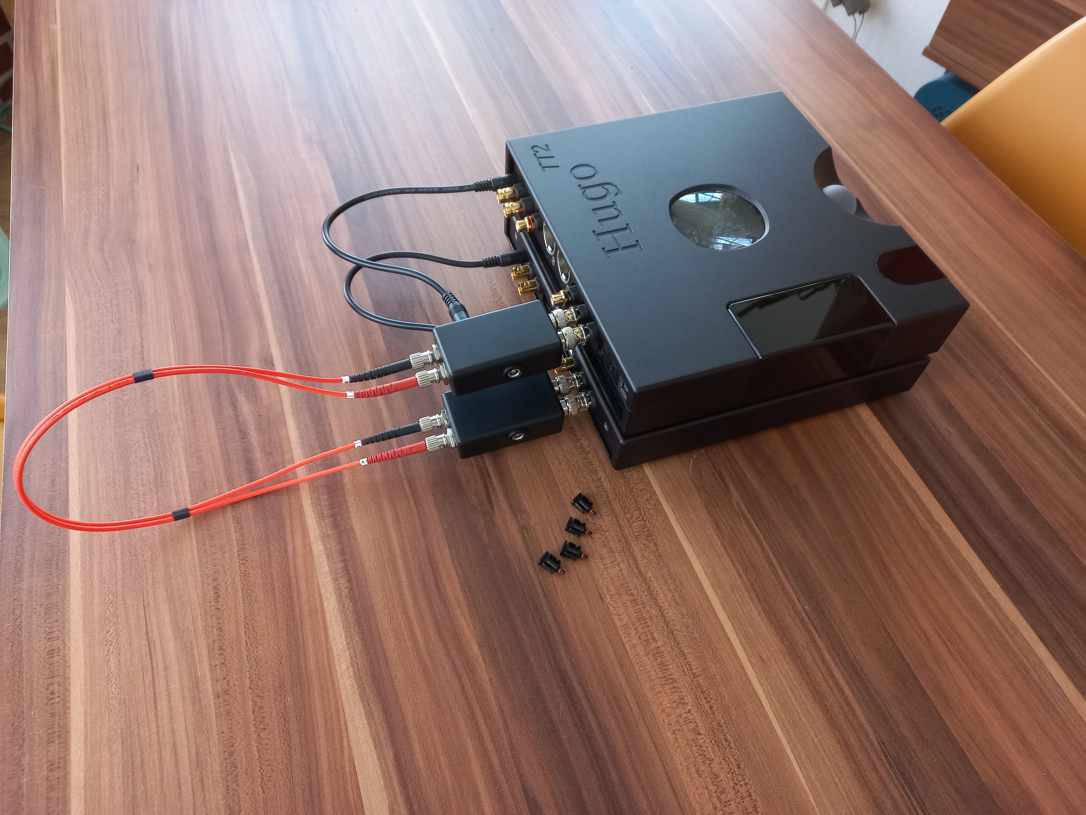
It uses the schematic as posted earlier and the PCB design for assembling the components. Instead of using a CNCed housing i went for plasic boxes which i found on Aliexpress as small as possible to be placed on a TT2. Also this can be added to a Qutest and Mscaler. This is a pluggable addon so TT2 and Mscaler wont need to be opened.

I stated earlier that i dont want ro use a external PSU or batteries and want to be on the same groundplane as TT2 and HMS so no groundloops can excist bringing RF in.

So i came to the idea to pass both 15v power feeds through my link boxes using two 5.5/2.5mm DC barrel sockets hard linked. Then tap the 15v and using a simple transistor and resistor devider to make 5v for the link.
For Qutest this can be skipped as it already uses 5V. I could use USB microB or C then.

Components used
20230106_150723.jpg


The hardest part is to solder the tiny Nand logic chips on the PCB, but using extra flux and leaded tin this goes much easier.
20230106_151901.jpg


After finishing the PCB's drilling holes in the boxes to fit the BNC's, Optics and DC sockets
20230106_165114.jpg


Jumping to the mounted PCB and components. It just fits leaving few space left.
20230108_121341.jpg


The receiver side has few componens as its circuit is integrated in the barrel.
It only needs power, a resistor to pull the output up to ttl level and a decoupling capacitor in the signal path.
20230108_121359.jpg


So closing the lids gives the final product
I got ready made 10A link cables for passing the power through.
20230108_122511.jpg


Both connected to Mscaler and TT2
20230108_130606.jpg


I placed the left DC socket on the receiver unit backwards to give space for a larger RCA plug on TT2
20230108_164335.jpg


With a 0.5m fiber attached
20230108_131537.jpg


Passing power through
20230108_132555.jpg


Now its time to test the link next to a ferrited coax solution..
20230108_132900.jpg


The sound impressions are for a next post.. perhaps by the new owner of this link set 😉

Thanks for reading!!
 
Jan 9, 2023 at 3:46 AM Post #109 of 170
Interesting project. Are you planning to make the pcb and or circuits available fo others with a diy inclination? BOM seems way cheaper than the commcerially available option.
 
Jan 9, 2023 at 4:02 AM Post #110 of 170
Shure
The schematic is already posted, it only needs the transistor addon

As for the PCB theres a list of gerber files for production, i see if i can post that here if its useful for someone
 
Jan 10, 2023 at 2:10 AM Post #113 of 170
I am interested for HMS and Qutest with long fiber cables.
These optic units are normally industrially used for datatransport over kilometers distance. I had to reduce the led current alot not to overdrive the receivers..
 
Jan 10, 2023 at 1:13 PM Post #115 of 170
Oh! Then plan B, squeeze all my up stream digital gear from the far end next to the speaker.

Oh i once had the idea of using 2 Mojo's, one at each mono poweramp next to the speaker and feed it one channel of the Dual data output over optical (at full Mscaling it comes seperated left and right channel in 384khz out of each BNC of the scaler)

Each Mojo then outputs one source channel in mono to its two line channels.

To adjust both mojo's volumes simultaniously i would use a pulse rotary with a turn direction swivel switch to send the pulses to either both Mojo's wired vol up or down buttons.

The benefit is losless isolated signal transport with extremely short wiring at the amp side.
I would even build the Mojo's inside my amps soldered directly on the PCB line input losing interconnect cables..
 
Jan 10, 2023 at 2:13 PM Post #116 of 170
Oh i once had the idea of using 2 Mojo's, one at each mono poweramp next to the speaker and feed it one channel of the Dual data output over optical (at full Mscaling it comes seperated left and right channel in 384khz out of each BNC of the scaler)

Each Mojo then outputs one source channel in mono to its two line channels.

To adjust both mojo's volumes simultaniously i would use a pulse rotary with a turn direction swivel switch to send the pulses to either both Mojo's wired vol up or down buttons.

The benefit is losless isolated signal transport with extremely short wiring at the amp side.
I would even build the Mojo's inside my amps soldered directly on the PCB line input losing interconnect cables..
Using mojo 2 you would even have an equalizer!
 
Jan 10, 2023 at 8:50 PM Post #117 of 170
To be clear :) I've a cd player, a HD player, notebook (RAMDisk OS - music control server), Intel NUC (RAMDisk OS - rendering and feed to the HMS) and HMS 7m always from the Qutest (next to the left speaker). pre-amp is between the two speakers.

Have to find a way to squeeze the digital stream in a tight 34" by 26" space. Maybe I can place the Intel NUC on top of of a air purifier (Because this is the nearest position to the TV) :), notebook on the floor, and forget about the cd player and HD player. Relay a dedicated line for the notebook, Intel NUC and HMS.

And if the two boxes can make me cry then I'd not mind all these hassles!

Btw, the box are made of plastic, can it prevent the RFIs sneak from the BNCs output to the BNC inputs?
 
Last edited:
Jan 11, 2023 at 3:26 AM Post #118 of 170
Btw, the box are made of plastic, can it prevent the RFIs sneak from the BNCs output to the BNC inputs?

Good point.
It might be possible, a tiny bit, only the DAC side would need it then. I simply could wrap a silver foil around the internals.. or cnc my designed metal box housing.

But this is a proto i made for another user to test with his TT2. And the sound is stunning
 
Jan 12, 2023 at 1:13 AM Post #119 of 170
But this is a proto i made for another user to test with his TT2. And the sound is stunning
Did the TT2 user cry? :)

Btw, guess you probably know, if metal box was used, wise user like me will ensure the weight of the box and fibre wires will not stressed the BNC inputs and outputs of the Dac and HMS!
 
Last edited:
Jan 12, 2023 at 2:17 AM Post #120 of 170
Did the TT2 user cry? :)

Btw, guess you probably know, if metal box was used, wise user like me will ensure the weight of the box and fibre wires will not stressed the BNC inputs and outputs of the Dac and HMS!
He will come get his set only half way next week.. and must be dying to try it😄

I hope he then post his impressions here

At least i got time for a thourough comparison to its and my Dave's amp sections
 

Users who are viewing this thread

Back
Top