Modifying the Xiang Sheng 708B [56K!!!!]
Feb 17, 2007 at 4:08 AM Post #31 of 223
Quote:

Originally Posted by dcheming /img/forum/go_quote.gif
"

Speaking of dropping voltage, the 6X4 seems to drop more voltage than the 6Z4 did since the B+ now measures around 195VDC instead of around 220VDC. Since the HV was too high due to the 110V transformer anyways, this will probably be for the best. I really need to find out what B+ this amp is supposed to have and go from there.


LOL! I was actually thinking last night how easy it would be to do this mod and forget this fact.
tongue.gif
That would be a bummer for sure since your amp would down until you got a 6X4.


I would imagine if the voltage isn't dropping to the point of not being able to properly operate the tube and/or cleanly drive the headphones, then it should be fine.

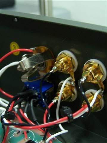
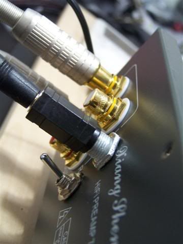
Just as a joke (since I wouldn't waist the time to ever go back to the 6Z4) you could install a DPDT switch on the back panel allowing switching back and forth between the 6Z4 and 6X4.
icon10.gif
 
Feb 17, 2007 at 10:23 AM Post #32 of 223
Just finished working on the heater voltage correction. All those resistors came in handy for testing. I was able to get both heater circuits pretty close to 6.30VAC.


Rectifier Tube

The new 6X4 had 7.22VAC for its heater voltage being directly fed by the transformer.

Here's the progression I tested:

1.0Ω = 6.63VAC
1.2Ω = 6.52VAC
1.5Ω = 6.36VAC

According to calculation the ideal resistance is 1.58Ω, which would give 6.30VAC.

The closest resistor I had was 1.5Ω, which dropped it to 6.36VAC.

So in my amp the best I'd be able to do here would be a 1Ω 2W + 0.47Ω 2W + 0.10Ω 2W all in series giving 1.57Ω, which would drop it to 6.31VAC.


Audio Tubes

The three audio tubes had 7.42VAC for their heater voltage being directly fed by the transformer.

Here's the progression I tested:

1.0Ω = 6.63VAC
1.2Ω = 6.47VAC
1.3Ω = 6.40VAC
1.39Ω = 6.35VAC

According to calculation the ideal resistance is 1.43Ω, which would give 6.30VAC.

The closest resistance I could do was 1Ω 5W + 0.39Ω 5W in series giving 1.39Ω, which dropped it to 6.35VAC.

So in my amp the best I'd be able to do here would be three 0.47Ω 2W in series giving 1.41Ω, which would drop it to 6.31VAC.
 
Feb 17, 2007 at 4:32 PM Post #35 of 223
Hi derek, mind teaching me how i can measure the voltage. What do i need.?

Quote:

Originally Posted by dcheming /img/forum/go_quote.gif
Just finished working on the heater voltage correction. All those resistors came in handy for testing. I was able to get both heater circuits pretty close to 6.30VAC.


Rectifier Tube

The new 6X4 had 7.22VAC for its heater voltage being directly fed by the transformer.

Here's the progression I tested:

1.0Ω = 6.63VAC
1.2Ω = 6.52VAC
1.5Ω = 6.36VAC

According to calculation the ideal resistance is 1.58Ω, which would give 6.30VAC.

The closest resistor I had was 1.5Ω, which dropped it to 6.36VAC.

So in my amp the best I'd be able to do here would be a 1Ω 2W + 0.47Ω 2W + 0.10Ω 2W all in series giving 1.57Ω, which would drop it to 6.31VAC.


Audio Tubes

The three audio tubes had 7.42VAC for their heater voltage being directly fed by the transformer.

Here's the progression I tested:

1.0Ω = 6.63VAC
1.2Ω = 6.47VAC
1.3Ω = 6.40VAC
1.39Ω = 6.35VAC

According to calculation the ideal resistance is 1.43Ω, which would give 6.30VAC.

The closest resistance I could do was 1Ω 5W + 0.39Ω 5W in series giving 1.39Ω, which dropped it to 6.35VAC.

So in my amp the best I'd be able to do here would be three 0.47Ω 2W in series giving 1.41Ω, which would drop it to 6.31VAC.


Feb 17, 2007 at 4:51 PM Post #36 of 223
Quote:

What does a high heater voltage do? Do the tubes burn out faster?


The heater runs hotter, shortening the life of the heater, which in turn shortens the life of the tube itself. Just like putting too much voltage into a light bulb.


Quote:

Thinking of getting a 6N3P-DR NOS tube, wondering if it's worth going for the cryo version?


I have very little faith, if none at all with "cryo" anything. As far as I'm concerned, it's just another gimmick to suck more money out of people.
 
Feb 17, 2007 at 6:37 PM Post #37 of 223
Did some changes and rewiring and I have got the cover up as well, should not be opening it up again until my upcoming CK2III and SOHA is completed...
icon10.gif
(Not unless DErek tempt me with the 6x4 and voltage adjusting mods
very_evil_smiley.gif
)

The default tubes for testing and the amp
100_2599Small.jpg


100_2598Small.jpg


The tubes configuration for my amp
100_2610Small.jpg


100_2609Small.jpg


100_2607Small.jpg


Some glowing pictures. . .
100_2618Small.jpg


100_2601Small.jpg


100_2600Small.jpg


The additional inputs so that my girlfriend can play with it

The Wiring
100_2612Small.jpg

The input
100_2611Small.jpg


Her ipod and the amp
100_2613Small.jpg
 
Feb 17, 2007 at 11:29 PM Post #38 of 223
Quote:

Originally Posted by zer061zer0 /img/forum/go_quote.gif
Hi derek, mind teaching me how i can measure the voltage. What do i need.?


Do you have a multimeter? All you have to do is turn on the amp and let it warm up for a few minutes. The easiest place to measure the heater voltage of the audio tubes is the 6N3 socket. You'll be using pins 1 and 9 which have the big space between them. Just set your multimeter to read voltage, select the AC option, and use the test probes to touch the exposed metal of pins 1 and 9 in between the socket and the PCB.

heatertestpointsvn1.jpg


Since you have the 220V version your heater voltage might be fine. What voltage do you use in your country anyways?

Your new wiring job looks a lot better. I like how you used a 1/4" TRS jack for the aux input to make it easier for connecting things like iPods. So how are those massive output caps sounding?
 
Last edited:
Feb 18, 2007 at 12:49 AM Post #39 of 223
For the rectifier's 1.5Ω 10W resistor I just mounted it to the side of the PS:

rect0zv5.jpg


rect1ra6.jpg


I'll probably mount both of the power resistors underneath the transformer later for a cleaner look. I wanted to try them out for a few weeks first before I went to the trouble to do so.

Last night I also swapped out the two 82KΩ 2W bleeder resistors for a pair of 160KΩ 2W ones.
 
Feb 18, 2007 at 3:41 AM Post #40 of 223
We use some 240v over here, nice pictures, i will try to measure to later on perhaps after te festive over here.

I am glad that the wiring looks decent, previously i was trying out the last time on the input thingy. I also changed the wires to some silver plated wires, I am not so gd with the cat5e ones. Hope i do get better along the way.

Gonna pause on it for a while before going into CK2III and the SOHA...
biggrin.gif


Quote:

Originally Posted by dcheming /img/forum/go_quote.gif
Do you have a multimeter? All you have to do is turn on the amp and let it warm up for a few minutes. The easiest place to measure the heater voltage of the audio tubes is the 6N3 socket. You'll be using pins 1 and 9 which have the big space between them. Just set your multimeter to read voltage, select the AC option, and use the test probes to touch the exposed metal of pins 1 and 9 in between the socket and the PCB.

heatertestpointsvn1.jpg


Since you have the 220V version your heater voltage might be fine. What voltage do you use in your country anyways?

Your new wiring job looks a lot better. I like how you used a 1/4" TRS jack for the aux input to make it easier for connecting things like iPods. So how are those massive output caps sounding?
smily_headphones1.gif


Feb 18, 2007 at 4:08 AM Post #41 of 223
Quote:

Originally Posted by zer061zer0 /img/forum/go_quote.gif
We use some 240v over here


So since your transformer is rated for 220V, but you're feeding it 240V you'll have the same problem with high heater voltage that we have here unfortunately.
 
Feb 18, 2007 at 4:12 AM Post #42 of 223
Quote:

Originally Posted by dcheming /img/forum/go_quote.gif
So since your transformer is rated for 220V, but you're feeding it 240V you'll have the same problem with high heater voltage that we have here unfortunately.


Do you think it might be a little worse since they're 20V higher where we're only 10V higher? Maybe pushing close to 8V to those heaters?
eek.gif
 
Feb 18, 2007 at 5:00 AM Post #44 of 223
Quote:

Originally Posted by zer061zer0 /img/forum/go_quote.gif
I dun quite understand how we can connect the resistors in line to the PS and to the heater pins, Derek can you show me another pictures.


So the yellow twisted pair coming from the transformer is the heater winding for the 6Z4 and 6N1 up front. The green twisted pair coming from the transformer is the heater winding that feeds the three audio tubes.

By cutting one wire in the twisted pair and inserting the resistor there we are basically putting the resistor in series with the the heaters. I would start with the audio tubes first. So what is the voltage of your audio tube heaters?
 
Feb 18, 2007 at 5:09 AM Post #45 of 223
Here's how I did the resistors for the audio tubes. I soldered about 6" of new twisted green wire to the audio board to give me more slack to play with. For the rectifier tube I de-soldered one of the yellow wires from the PS PCB, soldered about 2" of green wire in it's place and then soldered it and the yellow wire to the 1.5Ω resistor.

9934978.jpeg


I'll be able to calculate what size you need for this resistor based on what your heater voltage is. Let me know if you want some close up pics of the rectifier area.
 
Last edited:

Users who are viewing this thread

Back
Top