Modding my 0404: Can someone please verify
Mar 5, 2005 at 12:24 PM Post #61 of 101
Well if the regulators are 3.3V or 5V output then post regulator cap of 6.3V would be fine. For things you don't know, just measure them. PCI cards have 12V max so you should be able to get away with 16V most of the time. But there are parts of the 1010 card which I use which goes to the 1820m dock which are higher voltage so it's always wise to check.
 
Mar 6, 2005 at 5:12 AM Post #62 of 101
hi Ian,
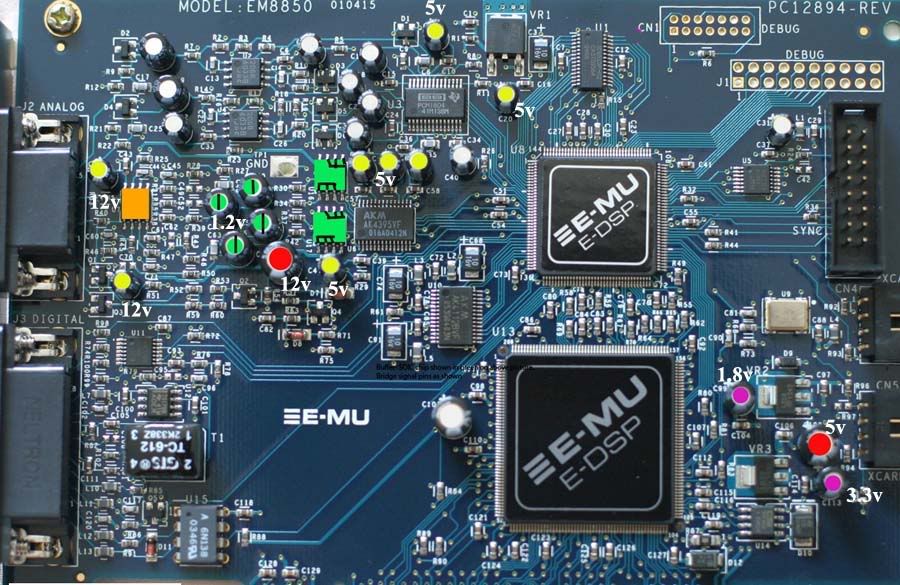
thanks for the advice. I measured across the legs of each cap. Does this look right?

0404volts.jpg
 
Mar 6, 2005 at 5:27 AM Post #63 of 101
Well I don't have these memorized or written down so I can't say if they are correct. How am I to refute a measuring device?
tongue.gif
 
Mar 6, 2005 at 5:31 AM Post #64 of 101
I was hoping you'd be able to tell me if they looked right on cursory inspection of the voltages
tongue.gif


anyway I was thinking of going full black gates on the card. would it be a good idea if I went with the N series on all the caps on the board? or should I throw in some FKs and what not into the mix?
eggosmile.gif
 
Mar 6, 2005 at 6:01 AM Post #65 of 101
Yes by glance it looks about right.

You have Sanyo OSCON already there. Not much point in going blackgate.

I generally like N more than FK. NX > N. NX-hiQ > NX. But you can't fit most FKs and Ns in those holes so it's not as you even could.
 
Mar 6, 2005 at 6:08 AM Post #67 of 101
Well I meant the leads don't go through the hole not the diameter of the cap. If it's too large, you won't be putting the caps in the front or back.
 
Jan 26, 2006 at 12:26 AM Post #68 of 101
Quote:

Originally Posted by lan
Well I meant the leads don't go through the hole not the diameter of the cap. If it's too large, you won't be putting the caps in the front or back.


Wel im about to order some os-con 10uF/16v SG caps to replace the yellow caps on the diagram. Will they all fit in on the main side, or even through the holes?

Im also getting panasonic direct replacement for the purple 47uF/16V, and red 100uF/25V, caps for direct replacement. Will these fit on the main side and through the holes on the pcb.

Btw. i intend to bypass the output caps, remove and bypass the outputs buffers, then wack on an lt1364 first before changing the caps.

One more thing. how do i measure this offset that everyone goes on about, and what are safe levels????

cheers
 
Jan 26, 2006 at 4:24 PM Post #69 of 101
Anyone
confused.gif
confused.gif
confused.gif


I really wana know how to measure the DC offset, and what it means. Plus i want to order the caps by tomorrow so they get here early next week.
??

ta
 
Jan 26, 2006 at 5:18 PM Post #70 of 101
A DC offset is a constant voltage superposed to the (AC) signal, relative to signal ground. The voltage level at no output is shifted, thus the term DC offset. If you want to connect headphones or speakers via an amp that's entirely DC coupled, you do not want this to be too large to avoid fried voice coils. The output coupling caps are there to eliminate any DC offset; single-digit mV readings across the cap should be safe (after the voltage gain stage, if any - you don't want it to be amplified, after all). Now coupling caps are not the most linear devices, particularly electrolytics (you need them to have a certain capacity to drive loads down to 600 ohm, and comfortably so) and those particularly when they are not biased (some DC across the cap - like a few volts - reduces the hysteresis considerably; yes, these things can distort like transformers). That they work as well as they do is only due to being overdimensioned quite a bit, thus very little voltage dropping over them in the frequency ranges that interest us. (Try building a simple R-C highpass with a 'lytic and measure the distortion for tones around and below the corner frequency. That won't be looking good even for nonpolar types I bet.)
 
Jan 26, 2006 at 6:52 PM Post #71 of 101
Quote:

Originally Posted by sgrossklass
The output coupling caps are there to eliminate any DC offset; single-digit mV readings across the cap should be safe (after the voltage gain stage, if any - you don't want it to be amplified, after all).


Great explanation, cheers.

So to measure the DC offset on my emu card i should take a reading from a cap that on is the left channel, and one on the right?
Going by the diagram, 9 posts above this one, i should take readings off the green caps next to the '1.2V' lettering (near the two green output buffers) ??

thanks

ad
 
Jan 26, 2006 at 7:26 PM Post #72 of 101
Those green caps look right... I just don't know why there are 4 of them there, the card only has 2 output channels after all and the coupling caps for the inputs are further up to the left of U2. I guess there's one for signal and ground per channel then. Oh, and now that I'm looking at the pic... ablaze has already measured the voltage across your caps, 1.2 V in this case. Looks like a decent bias for 'lytics, but not like something one should bridge.
 
Jan 26, 2006 at 7:51 PM Post #73 of 101
Quote:

Originally Posted by sgrossklass
Oh, and now that I'm looking at the pic... ablaze has already measured the voltage across your caps, 1.2 V in this case. Looks like a decent bias for 'lytics, but not like something one should bridge.


ye i thought it was those caps. With regard to the not bridging them above, i thought it was a well know mod that helped the sound and had no risks involved ?

ad
 
Jan 26, 2006 at 11:23 PM Post #74 of 101
Quote:

Originally Posted by adfinni
Btw. i intend to bypass the output caps, remove and bypass the outputs buffers, then wack on an lt1364 first before changing the caps.

cheers


I played around a little with the LT1364 in E-MUs and other devices. I found the chip has more DC offset than desirable. I can't remember the specifics right now. I would be cautious using this opamp without caps after it.

I originally bypassed the caps in my 0404, but I found that the DAC on the card put out too much DC offset to leave it this way. I installed Blackgate NX coupling caps later. If you are lucky enough to have a DAC with no offset than go ahead and bypass the caps. Most likely you will need the caps though.
 
Jan 27, 2006 at 11:16 AM Post #75 of 101
Quote:

Originally Posted by bg4533
I played around a little with the LT1364 in E-MUs and other devices. I found the chip has more DC offset than desirable. I can't remember the specifics right now. I would be cautious using this opamp without caps after it.

I originally bypassed the caps in my 0404, but I found that the DAC on the card put out too much DC offset to leave it this way. I installed Blackgate NX coupling caps later. If you are lucky enough to have a DAC with no offset than go ahead and bypass the caps. Most likely you will need the caps though.


Oh right, because i thought it was a safe mod that could be done and forgotten about. My lt1364 arrived this morning, so il check the DC offset in the next few days and see if i have to leave the output caps untouched.

Btw, what is a safe DC offset level ?

thanks

ad
 

Users who are viewing this thread

Back
Top