Modding a Musiland 01 US DAC
Sep 13, 2009 at 1:48 AM Thread Starter Post #1 of 19

mmerrill99

Member of the Trade: M2 Tech
Joined
Mar 2, 2006
Posts
1,233
Likes
46
I bought one of these for it's 24/192 asynchronous USB functionality & particularly this model as it has a PCM1793 DAC on the pcb which is fed I2S. Eventually, I want to route the I2S to another DAC (probably a Sabre - initially the newly released 2Vrms voltage out).

But before I get to that I decided to see what were the weaknesses of the DAC & how they might be improved.

First off this is powered from the USB cable which is an obvious weakness. The PS is actaually quiet good with 3.3V & 1.2V regulators to feed the Cypress & Xilinx chips. The USB 5V supply goes through some PS cleaning & filtering circuitry & is supplied to the PCM1793 DAC. +5V & -5V (which is also generated in this circuitry) is supplied to the OP275 op-amp output stage which acts as a low pass filter (to remove any frequencies above a couple of hundred KHz) & gain stage (which multiplies the output voltage by 1.83 to bring it upto 2Vrms).

I changed the capacitors on all the digital PS to Sanyo Oscons. I added in some extra capacitance for PS smoothing & filtering. I made an external socket which could take an external 5V power feed but connected straight through the USB D+, D-, ground pins (diagram attached). This made about a 10-15% improvement in the sound - taking away an edginess.

I next took out the Vcom 1uf capacitor as this is a critical capacitor - it decouples Internal Bias & Vref pin 14. The Vcom - seems to respond like signal passing caps - film caps for the clearer highs but need higher uF for decent bass response. I'll try a high uF electro with film bypass.

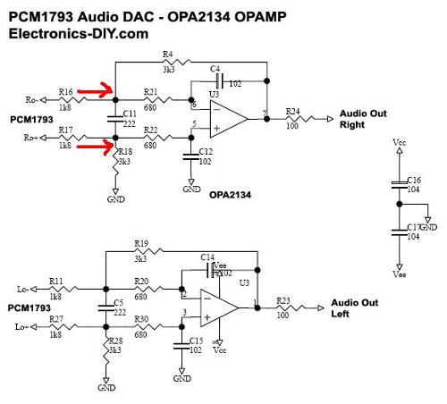
Finally, I bypassed the whole output stage and brought the differential Vouts from the PCM1793 DAC to a transformer via a low pass filter of 1K8 R on each differential leg with 1nF cap to ground on each (for a 88KHz cut-off). This sounds excellent, very natural. I'm using some transformers that I had for a preamp project but I've ordered a pair of Sescom MI-97 transformers on the recommendations here diyAudio - View Single Post - Experience with this DIY DAC ?
 
Sep 13, 2009 at 2:52 AM Post #3 of 19
Can you please share the pictures / further details on the output stage mod? Thank you!

Edit: Oh, and regarding "put some extra capacitors (10uf) at the PCM1793 supply pins", where did you add the caps? Were they soldered on C25, C28, and C29? Can I use slightly larger caps (33uf) instead?
 
Sep 13, 2009 at 12:27 PM Post #4 of 19
I wanted to post pictures her but the 19K limit made them stamp size & useless - I guess I'll go set-up a filesharing account & post there - I hate forums that force you to do this extra work.

The output stage mod may sound radical but it just involves moving 2 resistors on each channel & soldering wires to the vacated pads. All of which is very reversible & in fact I'm thinking of installing a switch or jumper which will allow switching between the external Transformer output stage or the internal op-amp output stage.

I have to be careful here as I'm using a new Tripath TA2020 based amplifier as well. However, I compared the transformer on one channel with the existin op-amp stage on the other and the relative difference between them is that the trafo is much more natural & lifelike. The op-amp sounds great but the trafo sounds excellent.

I tried 2 different trafos - one was a small Talema encapsulated 16VA toroidal mains trafo 115-0-115:22-0-22 so a 7:1 I connected to the secondaries to get a 1:7 because I thought I needed the gain. the sound was Ok but a little distinct on top & maybe a little missing at the bottom. I will experiment a bit more with this as there are some issues left to investigate.

The other trafo I tried is a special one from Dave Slagle, designed for a preamp but not yet installed - this gave amazing sound straight off but there is still some experimenting to be done with external resistors which seem to improve the sound yet again.

I've order a pair of Sescom transformers from ebay for $50 which were recommended & I'll be trying these at some stage.
 
Sep 13, 2009 at 6:50 PM Post #5 of 19
Quote:

Originally Posted by chipzahoy /img/forum/go_quote.gif
Can you please share the pictures / further details on the output stage mod? Thank you!

Edit: Oh, and regarding "put some extra capacitors (10uf) at the PCM1793 supply pins", where did you add the caps? Were they soldered on C25, C28, and C29? Can I use slightly larger caps (33uf) instead?


I attach a schematic of the output stage - I simply de-soldered the 1K8 resistors and moved them to the capacitor (see the red lines in the pic - do the same on the other side too) - this disconnects the whole output stage from the DAC chip. It leaves two empty solder pads on each leg (where one end of the 1K8 R was attached) free for soldering a 2 wires to. These two wires then go to the primary of a transformer & the secondary wires go to your amp. Repeat for other channel.

Quote:

Edit: Oh, and regarding "put some extra capacitors (10uf) at the PCM1793 supply pins", where did you add the caps? Were they soldered on C25, C28, and C29? Can I use slightly larger caps (33uf) instead?


I took out C30 & replaced with an Oscon & put some caps across Vin & ground on the Regulator chips.

 
Oct 21, 2009 at 11:19 PM Post #6 of 19
Here are my mods so far:
- powered from external 5V supply (currently SMPS) but will be trying a Shunt regulator or battery - external supply was the best upgrade so far for digital out
- tapped I2S signals & ready to link to external DAC (haven't done so yet for various reasons)
- have just received a Crystek 24MHz clock to substitute for the on-board 24MHz crystal : this will be run off a 3.3V battery
- substituted the op-amp output stage of the PCM1793 DAC with differential Vout direct to transformer: this was the biggest upgrade to the analog out sound.
- I was looking to use a ADUM4160 USB isolator but I'm told that it won't work even at the lower 24/192 speed?
 
Oct 21, 2009 at 11:21 PM Post #7 of 19
First shot shows the full board which I've done the following to:
- replaced digital PS coupling caps with OSCONS
- analog PS decoupling to PCM DAC with Nichicon Muse
- the Brown & Red wires are from the differential Vout of the DAC to the twin co-ax that connects to a transformer - so this is the new output stage & sounds WAY better than the op-amp o/p stage. I needed to move the two 1K8 smd resistors from their pads (see attached schematic). This now disconnects the op-amp o/p stage but if I want to reconnect I just need to jumper from where the wires are connected to the moved smd Rs. Easily reversible mod. The other channel has thinner wires running under the board. These wires connect to isolated pads that were exposed when the RCA connectors were desoldered from the board.
Last photo shows a close-up of the Xilinx chip where the I2S lines run to the DAC. I removed some of the overlying varnish on these tracks in a staggered manner, applied a touch of flux & solder & then soldered some fine wires onto these tracks (make sure you have tinned the wire & apply some flux to the wire - line it up on the exposed, soldered track & just a tip of a soldering iron will do the job - not difficult with a magnifier. I run the wires through vias, to the bottom of the board and connect to a molex push on connector


Oct 21, 2009 at 11:23 PM Post #8 of 19
I also put a socket (seen in the pic) on the Vcom pin of the PCM1793 as I heard that this capacitor influenced the sound - I can't say I've noticed much of a noticeable change among caps - maybe a better HF response using film?

I've marked with two red lines, the two 1k8 Rs that are moved down to join with either side of the smd cap, exposing the pads that the two wires are soldered to for the transformer output
 
Oct 21, 2009 at 11:29 PM Post #9 of 19
So far, the best mods : using external PS mod cleaned up both the analog & digital outs. Transformer output stage made a huge difference to the analog out but this depends on the transformers used - I'll be testing the Sescoms MI-97 & comparing against the Slagle transformers.
 
Oct 22, 2009 at 6:40 AM Post #10 of 19
Great job Jkeny!
beerchug.gif
 
Nov 6, 2009 at 7:26 PM Post #11 of 19
jkeny,

Did you figure out what is the format of the audio interface? Is it 24bit I2S?

You can tell by measuring how pins 26, 27 and 28 are set up (PCM1793 Data sheet page 15).

I guess I can do it myself, but I haven't opened the device yet :)
 
Nov 7, 2009 at 1:46 AM Post #14 of 19
A bit of an update before I change the 24MHz clock:
- I was using Dave Slagle made 80% Nickel based transformers for DAC o/p duties up to now. these are not designed for this role & are earmarked for a tube preamp.
- I bought a pair of Seccom MI-97 transformers off ebay for $50 which were recommended to me.
- Just tried them tonight & they are close to the Slagles. They might be more evenly balanced than the Slagles but it's a bit early to tell. The Slagles have a shimmering & extended HF which also seems to emphasise a background hiss coming from the laptop PS.
- some more tests & tweaking needed but I'm not disappointed with these Sescoms.
 

Users who are viewing this thread

Back
Top