Mini Portable Amplifier, with Discrete Diamond Buffers
May 21, 2006 at 4:45 AM Thread Starter Post #1 of 21

cetoole

1000+ Head-Fier
Joined
Nov 28, 2004
Posts
1,271
Likes
11
discretemini.png

discretemininosilk.png

discreteminisch.png


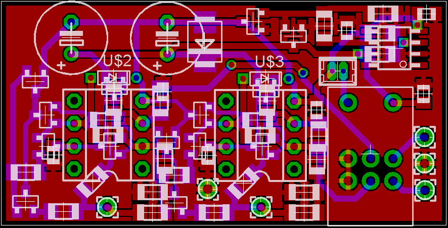
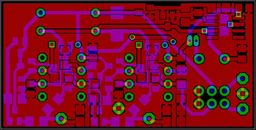
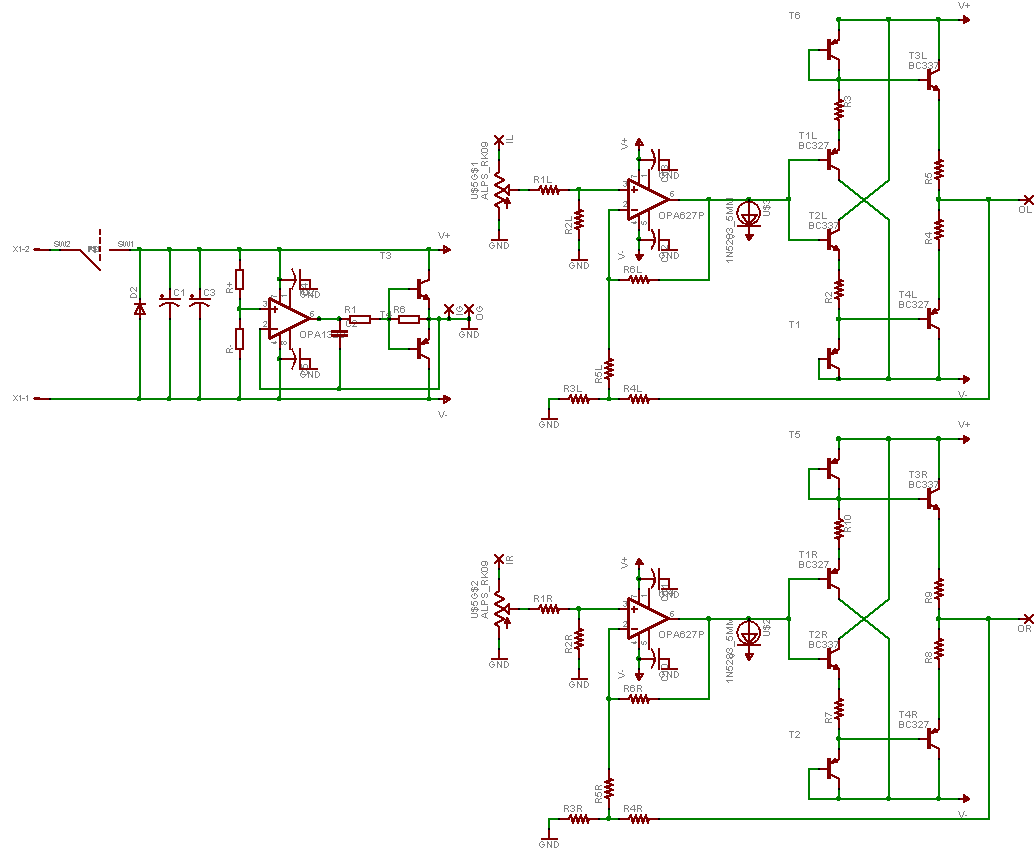
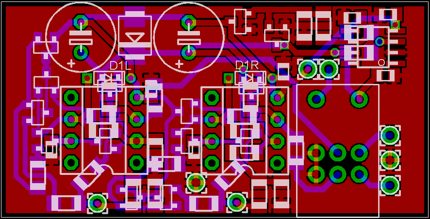
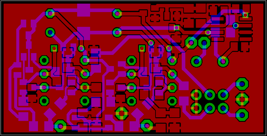
Been working on this layout for a while now, its already the second day
eek.gif
. Features are:
  1. DIP8 opamps for L/R
  2. SOIC opamp for ground, either use a high current single opamp, or a low current opamp with an emitter-follower in its feedback loop
  3. Bypassing on all opamps via 0805 ceramics right at the power pins to ground
  4. 1206 resistors everywhere
  5. Discrete Diamond buffers for L/R, with crd ccs, all transistors in SOT23
  6. 2 channel design, eliminates the need to isolate the input/output jacks, and reduces current draw
  7. No parts requirements that require sourcing from only one place, so no shortages like recently with the BUF634, TLE2426, and OPA551
  8. PCB measures 49mm x 25mm, so fits my favorite case for portable, the Hammond 1455C801, with 8xAAA batteries for a long runtime, and plenty of voltage swing into the majority of headphones we use portably.
 
May 21, 2006 at 11:05 AM Post #2 of 21
nOW this is great! I really like that hammond case! And the use of AAA's gives very large running times if using recheargeables.

Is this based in any known design?

I asked ATAT the same question: Where's the charging circuit?? It would be very usefull if using the hammond because it's a pain in the neck to open that case regularly!
 
May 21, 2006 at 11:29 AM Post #3 of 21
Very nice
biggrin.gif


I must say you are getting better and better at your designs and there is very little to criticize on there now and the only thing I would add is a trickle charger circuit as asked by MASantos and as you said you want it to fit that Hammond case, make the width of the board exactly the same size to slide in the rails of it and make sure you have a 2.5mm gap from the board edges to any components so that it actually fits in (Great way to test it out is to print off on paper the PCB and physically see how it fits in the case, I’ve learnt from some bad mistakes to make sure you get it to fit before finalizing it all)

Quite nice to see more people coming up with their own designs
 
May 23, 2006 at 3:24 AM Post #4 of 21
dude, that looks pretty damn impressive! good job
 
May 23, 2006 at 3:52 AM Post #5 of 21
I don't know if this is a stupid question, but as you're using the ALPS RK097 with this design, isn't the board going to make it hard to panel mount the input and output jacks (and whatever else) because it'll be in the way?
confused.gif


Other than that, impressive, as others have said.
 
May 23, 2006 at 6:51 AM Post #6 of 21
Quote:

Originally Posted by SubRosa
I don't know if this is a stupid question, but as you're using the ALPS RK097 with this design, isn't the board going to make it hard to panel mount the input and output jacks (and whatever else) because it'll be in the way?
confused.gif


Other than that, impressive, as others have said.


Yes, the position of the pot will make the input wires a bit more difficult to route than would be ideal, but that was one of the necessary comprimises I had to make when squeezing the size of the board down. It will probably increase the wire length by roughly 1 inch. Here is the new layout I did to ensure it will fit in the 1455C801, not quite as clean, but again, those are the comprimises one must make to get size down.
discretemini2.png

discretemininosilk2.png
 
May 23, 2006 at 7:16 AM Post #7 of 21
Got everything done for the proto panel cetoole. I should get the panel back in about 5 days, I'll ship it then so wait 7 days and you'll have your board. and I will have mine =)
 
May 23, 2006 at 12:38 PM Post #10 of 21
May 23, 2006 at 12:51 PM Post #11 of 21
The thread starter is a student so maybe we have a case here of good selfconfidence (and not so much experience).

I'm old enough to realize when I have to breadboard or prototype first. Nowadays I also try to simulate and this can catch big errors.
 
May 23, 2006 at 1:19 PM Post #12 of 21
Quote:

Originally Posted by peranders
The thread starter is a student so maybe we have a case here of good selfconfidence (and not so much experience).

I'm old enough to realize when I have to breadboard or prototype first. Nowadays I also try to simulate and this can catch big errors.


just concerned since there's a few new designs surfacing up in here, and finalized in a few days after initial schematics.
 
May 23, 2006 at 2:02 PM Post #13 of 21
hey peanders. I saw your comment and cetoole's thread on headwize and he says

"Ah yes, forgot to mention that, I just used that part instead of making my own package for this. As far as I can tell, it is wired correctly for that part."

in response to

"T6 T1 T5 T2 seem to be wired wrong."
 

Users who are viewing this thread

Back
Top