Mini Dac TDA1543 X 4 NOS
Mar 10, 2013 at 6:45 AM Post #901 of 1,063
@Lumos.
 
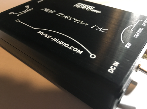
You cannot connect your HP's directly to this DAC.
The DAC must be connected to an amplifier,then your HP's plug into the amplifier.
biggrin.gif


May 9, 2013 at 8:56 AM Post #902 of 1,063
Been using this DAC with the Teradak power supply 9v for over a month now & bypassing the DAC & tube output on the CD player. Prefer this set up, which to me indicates the main influence is the DAC chip itself. Will stick with these older NOS chips from now on, sigma delta seems pointless. Would like to try the Valab luxury 8x1543 + reclocker & see if there is any further improvement. Another improvement I found after switching out a couple of weeks later was changing the digital cable from 1m to 0.5m. It was a lot better, which suprised me but I read somewhere, can't remember but 1m digital cable was the worst for some technical reason according to this particular expert, go figure.
 
 
May 12, 2013 at 1:12 PM Post #903 of 1,063
i see nothing special with the teradack psu. if you want the full benefit of a better power supply you should really mod the inside of the dac, focusing on the area around the regulator; changing out the smoothing caps, bypassing the adjust pin of the lm317 with 10uf+ caps ect. 
 
the optimal i/v resistor values at 6v should be 200ohm for vout and 246ohm for the vref. vout resistors can be bypassed with 1nf caps for further noise reduction. (some say this adds the cap sound but i found it to be the preferred solution)
 
since moving on from this dac I've been breadboarding my own 1543 dacs with battery supply, or 10 chips stacked with teddyreg, ect. and they all sound better than anything I had owned before.
 
I still have muse dac to thank for bringing me where I am, deep in sound heaven with only a shallow scoop on my wallet. 
 
May 25, 2013 at 5:54 AM Post #905 of 1,063
please help!!!
 
need the schematic of this muse mini dac dir9001 4 x tda1543, totally DOA
check for so many times the power supply and exchange the power supply 12V DC
 
is there sombody that can draw the schematic, im totally new in this
 
May 25, 2013 at 7:24 AM Post #906 of 1,063
Can I please second Hendrik's request for a schematic of this DAC?
 
I received my MUSE Mini DAC TDA1543x4 DIR9001 a couple of days ago and it only works via optical, not coax.  I believe it's faulty.
 
When running coax input the un-lock light remains on - I've confirmed the source connection is fine using another DAC, tested different sampling rates, output formats etc no difference.
 
Took 5 weeks to get here, so I'm not sending it back.
 
Can anyone please help out with a schematic and some possible suggestions?  I'm sure it would only be a simple part to fix, given it's working fine on the optical input.
 
May 27, 2013 at 7:53 AM Post #907 of 1,063
****...
 
it's DOA, so the seller needs an movie to see if it's really dead...
I have ask seller to give me the schematic, he told me to ship it back....
another 10 week wait 5 weeks back and 5 weeks ship...
 
May 28, 2013 at 3:12 AM Post #908 of 1,063
I don't have a schematic but from looking inside my own Muse, there's a logic gate which handles the switch over between optical and coax. The problem could be the switch or the gate (which from memory is 74HC00).
 
 
May 28, 2013 at 11:52 PM Post #909 of 1,063
Quote:
****...
 
it's DOA, so the seller needs an movie to see if it's really dead...
I have ask seller to give me the schematic, he told me to ship it back....
another 10 week wait 5 weeks back and 5 weeks ship...

 
I'm in exactly the same situation - took 5 weeks to get to me.  The seller requested a video so I made one, and now I'm waiting another week until their supplier returns, before I find out.  I would rather attempt to repair than wait another 10 weeks if I get asked to ship it back. Especially since there's a high chance any repairs could be very cheap to make.  Not to mention the silver-lining being I can learn more about the DAC.
 
Quote:
I don't have a schematic but from looking inside my own Muse, there's a logic gate which handles the switch over between optical and coax. The problem could be the switch or the gate (which from memory is 74HC00).


Thanks for your reply Sapientiam, I can see from reading this thread that you are most knowledgeable when it comes to this DAC.  
 
I can get a 74HC00 for about $1 locally, do you suggest I first replace this component and then see what result it gives me?
 
May 30, 2013 at 3:15 AM Post #910 of 1,063
Quote:
I can get a 74HC00 for about $1 locally, do you suggest I first replace this component and then see what result it gives me?

 
It would be most unusual (in my experience) for such a chip to have died in-circuit. I'd be more inclined to believe the switch had failed or that there's a poor solder joint on it or that a PCB track has gone open circuit. Do you have a multimeter (or an oscilloscope) which you could use to check the logic levels on the chip?
 
May 30, 2013 at 8:05 AM Post #911 of 1,063
Quote:
I haven't done anything to the layout, just changed the led to blue and added a power on/off switch. But the one i'm sending away next I'm going to change the voltage resistors so as to lower it to about 7.13V for the chips (510 Ohm> 470 Ohm gives 7.65V>7.13V).

Oh, and i gave it some little rubber feet (5mm sticky bumpers). I don't like it scratching sound. It's all just little touches, but that all makes it just a bit nicer.

So, done the volt-mod. I added a 4k resistor to the 510 Ohm on the side (see page 12)
1000x500px-LL-9c8adcf1_2011-02-1314.42.44.jpg


1/510 + 1/4k= 1/455
1.25* (1+(455/100))=6.94 V
Just a little bit more safety-margin.

Jeep,
 
just to be sure, you change the value of R1 (510) and add (4K) that mean R1 must be change for 2.5K
correct me if im wrong
 
thx
 
May 30, 2013 at 7:59 PM Post #912 of 1,063
Quote:
 
It would be most unusual (in my experience) for such a chip to have died in-circuit. I'd be more inclined to believe the switch had failed or that there's a poor solder joint on it or that a PCB track has gone open circuit. Do you have a multimeter (or an oscilloscope) which you could use to check the logic levels on the chip?

I'll buy a multimeter locally tomorrow and read up on how to use it to test the switch.  I've never used one and don't have a background in electronics, I'm trying to learn as I go along.  I did inspect the board but could not see any dry joints or faults (with my limited experience).  
 
It might be the switch then if it's giving me that extremely small, split-second blip of sound when I'm flicking the switch from optical to digital?
 
May 31, 2013 at 12:01 AM Post #913 of 1,063
Yeah it might be - but if you get a short burst of sound with it in the 'coax' position my suspicion would fall on the input signal conditioning stage. If I recall correctly one of the HC00 gates is used as a linear amplifier to boost the 0.5V S/PDIF signal up to logic levels - there's an input capacitor to this stage. It could be there's something wrong with this capacitor or the biassing (via a feedback resistor). This is something that might well be picked up if you took a digital multimeter to the HC00 and measured voltage levels.
 
 
May 31, 2013 at 4:48 AM Post #914 of 1,063
Quote:
Yeah it might be - but if you get a short burst of sound with it in the 'coax' position my suspicion would fall on the input signal conditioning stage. If I recall correctly one of the HC00 gates is used as a linear amplifier to boost the 0.5V S/PDIF signal up to logic levels - there's an input capacitor to this stage. It could be there's something wrong with this capacitor or the biassing (via a feedback resistor). This is something that might well be picked up if you took a digital multimeter to the HC00 and measured voltage levels.


Hi Sapientiam, I've taken the case off and had a look.  I did notice something a bit strange on one of the capacitors - I took a photo of it here http://i.imgur.com/ASV9JJ0.jpg  - does that look like it could be an issue?  I can take more photos if needed.  I wasn't sure it was just some superficial damage during the manufacturing process...but that capacitor is close to the 74HC00 chip.  Interested in your thoughts on this.
 
Jun 1, 2013 at 3:59 AM Post #915 of 1,063
Looks like your PCB has been re-worked at some point. The damage to that capacitor looks consistent with someone taking a hot iron to the DIR9001 maybe to fix up a dodgy solder joint? It could indeed be a problem, seems rather too deep to be just superficial damage. If you've got your multimeter yet you could try checking for a short across the melted cap.


Users who are viewing this thread

Back
Top