Mini Dac TDA1543 X 4 NOS
Mar 1, 2013 at 10:00 AM Post #886 of 1,063
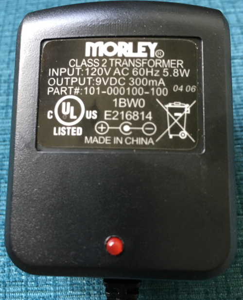
I have just received and I am listening to my muse tda1543 x4 in my headphone rig (usb asynchr VLINK II -> toslink muse tda1543 x4 with linear power supply 12V/1A ->Schiit Lyr + hifiman HE-4 orthos)
 
As you can see above muse has the best possible conditions to work (linear power supply and perfect digital input signal (jitter) with full galvanic isolation thanks to toslink)
 
From the first notes this is amazing experience how smooth female vocals can be comparing to delta-sigma dacs, everything is so natural and effortless despite of low parameters on paper
 
Amazing soundstage and depth, thrilling timbre and realism
 
I have one question, from time to time there is small distortion when there is high dynamic peak - have you experienced that ? I read something about bad value of output resistor (when there are several tda1543 together)
 
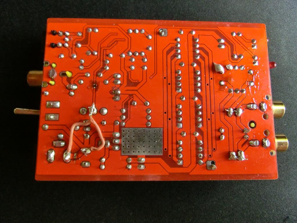
I can easily remove and solder proper one - will that help ? Could you help me identify it if I put the photos of the inside ?
 
I was also thinking about shorting output caps since Schiit LYR has DC servo inside (so should be input and output dc coupled if I am right) - what do you think ?
 
edit:
 
Checked everything inside, 2 chips didn't even touch the radiator - resolder some caps and corrected that ... now cooling of all chips is great
 
Checked Vout @ LM317T - 7.68V, come on, it gets extremely hot also ...
 
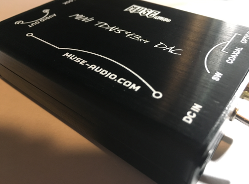
PCB from 2010/01, DC JACK says 15-18V (but unit comes with 12V power supply, I am using my own linear power supply 12V/1A - maybe the voltage is too low now ? shell I use 15V ?)
 
2x680Ohm @ outputs -> I think these are responsible for clipping when there is some dynamic peak or near 0dB recording ... but I don't know whether I should use 250 or 460 ohm resistors from what I have read (I would also decrease LM317T output voltage - I guess this voltage is used by the tda1543 chips, is it R01 ?)
 
Mar 3, 2013 at 8:17 PM Post #887 of 1,063
The LM317 needs at least 2V across it to function - any more than that will make it hotter. So you definitely do not need a supply of 15V, to keep it cool the best supply would be 10VDC, Many supplies will have appreciable ripple on the output so 12V gives a fairly safe margin for that.
 
As each TDA1543 contributes 2.3mA with 4 in parallel we get 9.2mA as the total current swing. Into 680R that's about 6.3V peak-peak. The compliance range is from 1.8V to VDD-1.2 which in your case gives 4.68V (because VDD is 7.68). So yes you will get clipping on digital peaks. Using 470R instead of 680R will reduce your swing to 4.3V - no clipping there but you also need to set the mid-point to precisely half-way between the compliance limits. In your case this is 4.1V which will result in swinging between 1.95 and 6.25V. You set the mid-point with the resistors connected to pin7s of the DAC chips.
 
Mar 4, 2013 at 12:22 AM Post #888 of 1,063
Quote:
How does the sound quality from this unit, stock and/or modified, compare to something like the ODAC or the MS2+?

No contest, the modded muse is better than both.  I've sold both my odac and hrt msii+.
The soundstage is wider and higher, more dynamic, deeper and better controlled bass and smooth smooth smooth.
 
Mar 4, 2013 at 5:09 AM Post #889 of 1,063
Quote:
No contest, the modded muse is better than both.  I've sold both my odac and hrt msii+.
The soundstage is wider and higher, more dynamic, deeper and better controlled bass and smooth smooth smooth.

I did some A/B-listening with my Muse 4xTDA1543 and my ODAC this weekend. I noticed that when I use my very analytical TZAR 350 IEM's the ODAC becomes too clinical and analytical, almost metalic and digitally sounding. The MUSE gives much more listening pleasure and no listening fatigue. So I can definitely confirm the SMOOTH sounding MUSE. 
 
Mar 4, 2013 at 9:55 AM Post #890 of 1,063
I agree, to my ears the difference with the odac sounds analagous to the difference between the sound of mp3 and vinyl.
 
Mar 5, 2013 at 6:34 AM Post #891 of 1,063
Quote:
The LM317 needs at least 2V across it to function - any more than that will make it hotter. So you definitely do not need a supply of 15V, to keep it cool the best supply would be 10VDC, Many supplies will have appreciable ripple on the output so 12V gives a fairly safe margin for that.
 
As each TDA1543 contributes 2.3mA with 4 in parallel we get 9.2mA as the total current swing. Into 680R that's about 6.3V peak-peak. The compliance range is from 1.8V to VDD-1.2 which in your case gives 4.68V (because VDD is 7.68). So yes you will get clipping on digital peaks. Using 470R instead of 680R will reduce your swing to 4.3V - no clipping there but you also need to set the mid-point to precisely half-way between the compliance limits. In your case this is 4.1V which will result in swinging between 1.95 and 6.25V. You set the mid-point with the resistors connected to pin7s of the DAC chips.

Right... now I'm confused. It's been said on here before that...
the silk screen says 680R. Its a bit higher than it should be to avoid clip. As a rough rule-of-thumb, a TDA1543 (passive I/V) should have I/V resistor of 1k divided by the number of paralleled DACs. In this case, with 4 DACs, 250R is about right.
 
So should I be using 250R in place of the 680R? Or in place of the 390R?
 
Some advice on the correct values to replace the 680's and the 390 would be really useful if anyone has the time... :)
 
Mar 5, 2013 at 7:39 AM Post #892 of 1,063
The rough rule of thumb is for the nominal 5V supply - but you're running at 7.68V which gives more than twice the compliance available (2V vs 4.68V). You certainly won't get any problems running at 250R - depends if the extra swing is useful to you.
 
Mar 5, 2013 at 7:47 AM Post #893 of 1,063
Quote:
Right... now I'm confused. It's been said on here before that...
the silk screen says 680R. Its a bit higher than it should be to avoid clip. As a rough rule-of-thumb, a TDA1543 (passive I/V) should have I/V resistor of 1k divided by the number of paralleled DACs. In this case, with 4 DACs, 250R is about right.
 
So should I be using 250R in place of the 680R? Or in place of the 390R?
 
Some advice on the correct values to replace the 680's and the 390 would be really useful if anyone has the time... :)

My latest muse dac I received last week has a black pcb and in the 390R position was actually a 470R resistor, FWIW. Taking a brief listen stock I didn't notice any clipping.
The 680R are the same.
 
There was some discussion on diyaudio about this topic (can't recall the title), in which one person used values in the 200-240R range for all 3 resistors.
 
I believe there was some variability on the precise value from dac to dac and a temporary trimmer pot had to be used to find the exact value and a permanent resistor subsequently soldered in.
 
Mar 5, 2013 at 10:14 PM Post #894 of 1,063
Started the modding and took a long listen, definitely some distortion.  470R and 680R will all get replaced.
 
Mar 5, 2013 at 11:04 PM Post #895 of 1,063
Hi All,

Just wondering if anyone can help me out. I have a NAD c375BEE amp. I am trying to determine if the RCA inputs have DC input coupling caps or not?
 
Obviously, I want to be sure of this before I remove the output caps on the Muse and connect to the amp! I have looked through the manual, NAD site and photos, but am not 100% sure.

Thanks in advance.
 
Mar 6, 2013 at 4:14 PM Post #896 of 1,063
Replaced the default 470R with 280R and got a lot of distortion- sounded horrible.  Went back up to 390R which is what is printed on the PCB and sounded good.  Then tried 423R and the sound got better, maybe a touch less dynamic than 470R but after 15min of listening could hear no distortion.  So, I'll solder in 423R and take a long listen.
 
 
Mar 7, 2013 at 1:46 AM Post #898 of 1,063
Yes, it should be 390R, but the latest one I bought has a black PCB and 470 instead of 390 (which is what's printed on the PCB).


Users who are viewing this thread

Back
Top