


]eep
Headphoneus Supremus
I already did on page 16 (top)
http://www.head-fi.org/t/512389/mini-dac-tda1543-x-4-nos/225#post_7312137
http://www.head-fi.org/t/512389/mini-dac-tda1543-x-4-nos/225#post_7312137
It's not so much a 'muddying' of the sound... the rolled-off treble extension and a lack of definition in the lower bass doesn't suit me. To be honest I'd be very surprised if the grounding mods can help in this regard - every NOS DAC that I've heard has been very similar in this regard.
I can see how they would sound good with some music types, but at this stage it simply isn't resolving enough for me and my choice of music.
I will look into the grounding mods when time permits, and perhaps some of the resistor replacements as outlined earlier in the thread. I need to get some other audio projects out of the way first.

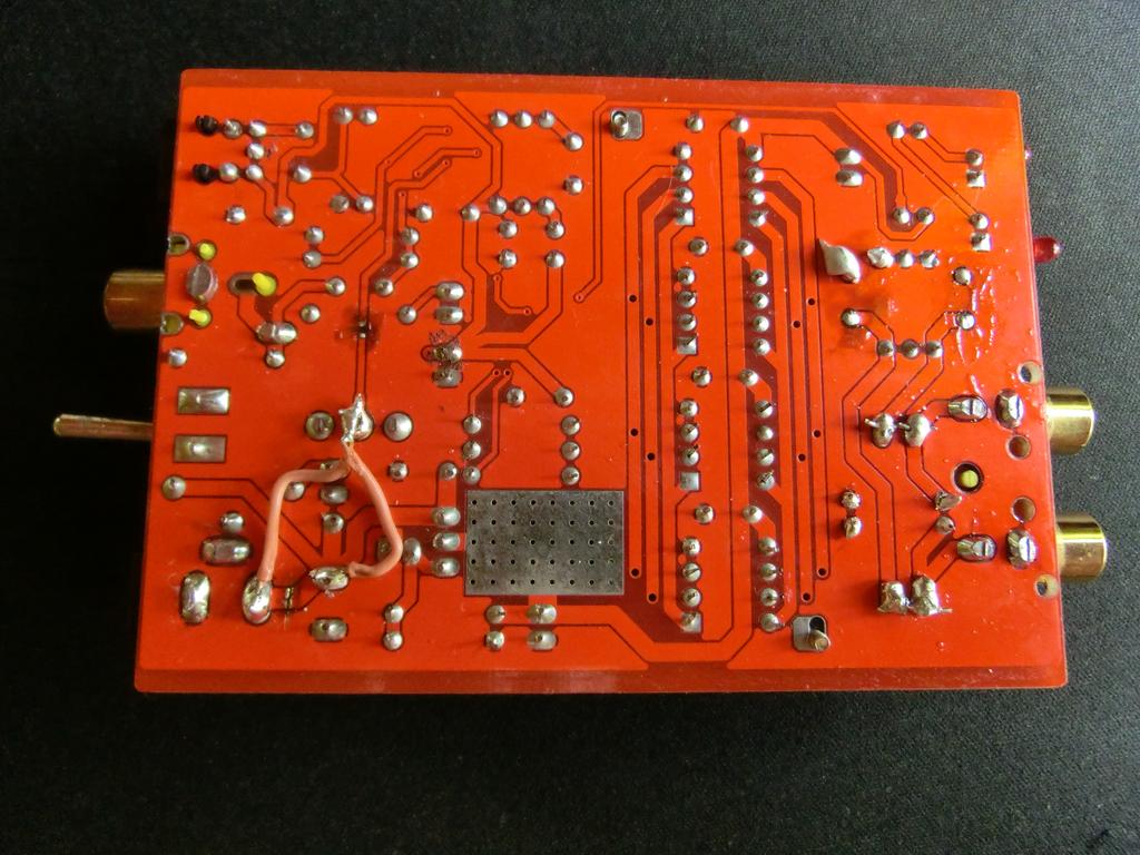
Sapientam, you'r not really helping with your secrecy. I keep looking at the photo's but I keep seeing things that make no sense to me. Why do you keep me guessing like this.
- I can see you made some crude cuts on the pcb but I can't see what you cut. The traces aren't visible.
- On the TDA you have some bare wires across pin 4 5 6 and 7. So what pins are shorted together?
- And where is the wire on C9 going to?
- What did you do near U03 (what was there anyway)?
- C8 and C9 are just removed, not shorted right?
- where is the wire on C6 going to? Why not simply short C6 and C7 with a blob of solder or a short wire. Or pin 6's and 8's straight to the outputs? No traces, no solder no muck.
Can't you make a drawing in the photo per mod (if needed a color per mod) to show what you did? Like I did on page 24...
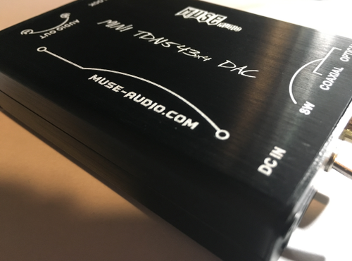
Yes the Muse does have that characteristic. Yum. I would still be using it but Floyd came out with the Immersion sets in hi-rez so I auditioned a bunch of budget dacs and chose the Dacport LX, which has turned out better than any dac I've had so far including the DAC19MK3 and CS4398 diy w/ output transformers, etc... so time to say goodbye to the Muse.


I also been into other budget DACs.
Another gem is the AK4396 DAC. You can find them on eBay very inexpensive, as a board or fully assembled.
It is easy to listen to like the MUSE. It has all the 'air' and none of the 'glare' of OS DACs.
With all the noise about the Schiit Bifrost with its bigger brother AK4399 chip, this DAC may just be the ticket for guys on a slim budget.

I'm not accusing you of malice. Just laziness. I can tell from the pictures
Thanks for the clarification.
So, if I get it, you connect pins 6=left and 8 =right to ground via an invisible 1kOhm resitor. But where do R19 and R20 come in?
If I would connect all pins 6 together direct to output and short it to ground via a 1k resistor, that would do it? Or is 250 enough (since you use 4 R's in parallel).
Wouldn't it be easier just to clip the legs (4, 7) 6 and 8 and solder them to a seperate wire? That way I could bypass all PCB traces from the analog signal path. I could use some decent wire for that (and some simple wire for ground).
Oops nr 1: C15 etc should connect pin 5=V+ to ground so clipping the leg means I have to lift that one and connect it to the groundwire too.
What value do you use from pin 7=Vref to ground? 330?
Plz explain in laymans terms, I'm not trained in electronics. I'm not stupid but sometimes you electronicsbuffs cut too many corners for me.

 ) from Toroidy.pl to my little DAC , and aluminium chassis, in spare time I will put DAC in this new chassis.