Mini Dac TDA1543 X 4 NOS
Oct 4, 2011 at 11:37 AM Post #691 of 1,063
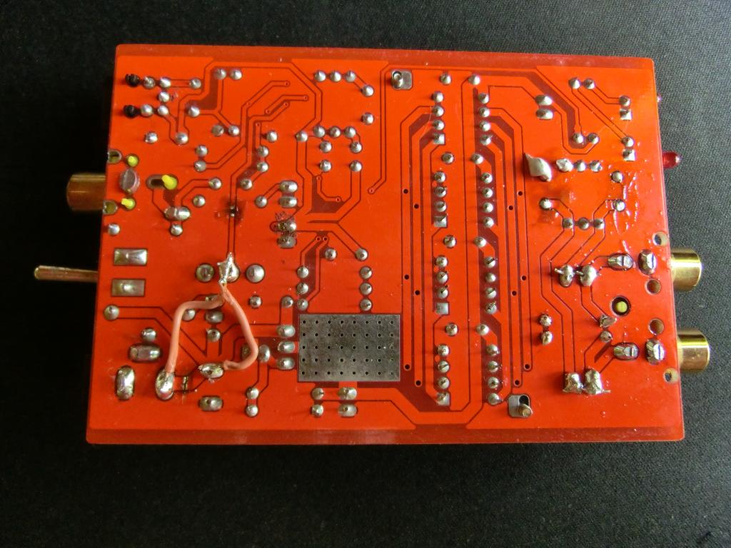
Thanks for the photos It helps to see the actual mods.
 
If I rolled up strips of tin foil and taped them in place with insulating tape, would that short out the caps without using solder?
 
Ideally, I'd just like to see if/how the mods work without making any permanent or visible changes.
 
Oct 4, 2011 at 10:07 PM Post #692 of 1,063


Quote:
If I rolled up strips of tin foil and taped them in place with insulating tape, would that short out the caps without using solder?


I very much doubt that'd work reliably. I've thought about it and can't think of a decent solution that doesn't involve solder.
 
@proid - what's wrong with your DAC already answered in post #685. You shorted the power supply - need to remove 4 shorts across caps. Solder sucker or desoldering wick is your friend.
 
Oct 5, 2011 at 1:24 AM Post #694 of 1,063
Yes, you're right. I took out those resistors because I wanted more flexibility about adding more DACs if I felt inclined. Also the grounding of those resistors is crucial to getting good sound.
 
If you look very closely I've soldered some very small SMT resistors vertically on pins 6,7 and 8 of the TDA1543s. They're 1ks (from memory). So the parallel effect is I have 250R for I/V and the same for current setting. But I've reduced the supply to the DACs on this one, no longer the blisteringly high voltage it came with. I did this for a couple of reasons, but mainly to give me some headroom to install passive RC filters on the input to the regulator (LM317).
 
Oct 5, 2011 at 5:07 AM Post #696 of 1,063
Modding by regrounding is in my experience the best bang there is for the buck. Because the buck is just some thin wires. Of course not an insignificant investment in time is involved, with potential frustrations when the groundplane isn't as severed as you'd been hoping - on this board its both sides of the PCB. But the resulting sound is its own reward.
 
Oct 6, 2011 at 10:16 AM Post #697 of 1,063
Your photos are great. I can't even pretend to understand what you've done but it helps to see the finished work.
 
I somehow missed hearing about removing those caps at C8 and C9. Does that have a similar effect to removing the ones at C6 and C7? I'm wary of those just in case my amp (or any others I may try to connect to) doesn't have the requisite caps on their inputs.
 
I'd like to get a bit more bass out of my DAC. The old stereo it's going into predates all that superbass type stuff so it can be a bit lacking in that department. And the five-band EQ on it isn't very good. As a result, I'm having to EQ it OS-side and I'd prefer not to.
 
Looking at what you've done with the TDA's am I right in saying you desoldered pin 4 on each, lifted it up from the PCB, then wired them back to that point on R01? Is the wire on the underside of the PCB running back to near the output a required step of that?
 
Oct 6, 2011 at 10:21 AM Post #698 of 1,063


Quote:
Modding by regrounding is in my experience the best bang there is for the buck. Because the buck is just some thin wires. Of course not an insignificant investment in time is involved, with potential frustrations when the groundplane isn't as severed as you'd been hoping - on this board its both sides of the PCB. But the resulting sound is its own reward.


I'm totally newbie in these thing, i only know how to solder but i really want to push it to the limit. So can you give me some detail about your mod, which one make the biggest improvement to the sound and some instruction how to do it. Thanks 
biggrin.gif

 
Oct 6, 2011 at 11:41 AM Post #699 of 1,063
Yeah the no.1 mod here is chucking out those 0.0022uF caps on the outputs (to ground). When they've gone, the soundstage appears. I suggest do this first - if you don't notice any difference then you're really going to be wasting your time doing the rest because the other mods are a bit more subtle than this one.
 
Another mod I've done which I consider definitely worthwhile is restoring absolute phase. The TDA1543 inverts when used with passive I/V because the datasheet shows its intended operation is with an opamp I/V which inverts the signal. If you're feeling brave that's not a very difficult mod to do but it does involve lifting some pins on the SO14 device near the switch. Along with that I attenuated the I2S lines to the DACs in an attempt to reduce digital-analog crosstalk. Such mods have been practiced by practitioners of TDA1541 circuits over on diyaudio.
 
Next up is regrounding the outputs and inputs. This is more tricky because of all the ground fill copper cutting that's needed below the RCA phono sockets and power supply inlet, on both sides of the PCB. The aim is to reduce or eliminate common impedance coupling by enforcing star grounding. Having done this then digititus is reduced and the sound gets sweeter and more endearing to listen to. I regrounded the DAC 0V connections too, just to complete the effect. In general, PCB ground fills are a bad thing for sound coz you're never quite sure what currents are going where.
 
Lastly there are some mods which I do anyway which I'm not sure make a difference to the sound but give me a sense of satisfaction for doing them. This includes some passive filtering on the input to the DAC regulator, which means reducing the supply voltage (by about 1V) to the DACs.
 
If you need more explicit details on these ones, let me know and I'll endeavour to help. I might even take some new pics to show the latest mods which aren't on those pics already up.
 
Oct 6, 2011 at 11:58 AM Post #700 of 1,063


Quote:
Your photos are great. I can't even pretend to understand what you've done but it helps to see the finished work.
 
I somehow missed hearing about removing those caps at C8 and C9. Does that have a similar effect to removing the ones at C6 and C7? I'm wary of those just in case my amp (or any others I may try to connect to) doesn't have the requisite caps on their inputs.
 
I'd like to get a bit more bass out of my DAC. The old stereo it's going into predates all that superbass type stuff so it can be a bit lacking in that department. And the five-band EQ on it isn't very good. As a result, I'm having to EQ it OS-side and I'd prefer not to.
 
Looking at what you've done with the TDA's am I right in saying you desoldered pin 4 on each, lifted it up from the PCB, then wired them back to that point on R01? Is the wire on the underside of the PCB running back to near the output a required step of that?


Thanks for your compliments 
wink.gif
 If you're curious about what any of those mods do then ask and I'll do my best to explain them. 
 
I took out C6 and C7 because I don't much like passing audio through electrolytics unless I absolutely have to. But I don't think having them in is as bad for the sound as having C8 & 9 in. Those last two are the real killers for reasons I don't quite yet understand. Don't take out C6&7 unless you're sure the thing your Muse is connected to can handle large DC offsets - meaning does it have a capacitor on its input? If in doubt, leave them in. More perceived bass might come from reducing the sibilance level which tends to go down with regrounding.
 
On the TDAs yeah I wanted each to have its own dedicated ground path back to the star earth I set up on R01. As its designed, currents to/from other stuff share that connection through the copper fill on the PCB. The output regrounding wire is independent - that just routes the ground of the output RCAs directly back to the star. As the I/V resistors are now soldered to each DAC individually, they return to the 0V via the new yellow wires to pin4 too. I'm not yet sure I've got the optimum arrangement for this yet, it might be better still to have a dedicated wire for the ground return of those 4 1k resistors. I might have a play and a listen....
 
 
Oct 6, 2011 at 10:56 PM Post #701 of 1,063
i'm feeling brave! which pins are those on the so14?
looks like a wire is soldered across pins 1-4 for one  of the tda's? (the top one)
think regrounding those 4x (c15,16,17,14) would make a diff?
 
i think someone else on another forum recommended to change the diode to a uf4007/sf4007. i have one on order but not sure what the potential sound outcome will be heh.
 
Oct 7, 2011 at 4:40 AM Post #702 of 1,063

 
Here you can see what I fiddled with for the second round of mods. This is the current state of play. The extra wires you noticed on the top TDA are part of the I2S attenuation network, under the 0V wire are SMT resistors. If you want to do this mod I'll have to check which values I ended up with.
 
You can see on the bottom left SO14 the pins which were lifted ahd connected to +3.3V (pin14). This chip is an HC00 quad NAND. Because I removed the switch I no longer needed one of the gates so that now does duty to invert the audio stream and render the whole DAC true phase.
 
I can't think why changing the diode would have any effect - I think its only there to prevent reverse polarity supply being applied, but I'm not totally sure. As for regrounding the 4 caps - I dunno. Suck it and see :)
 
Oct 7, 2011 at 6:25 AM Post #703 of 1,063
since i would be keeping the switch, i'd need to:
lift pins 9&10, then solder 9&10 together with vcc(pin 14)? srry, it's hard to see and i'm new this as well heh. nonetheless, i very much appreciate your insight in this.
 
"suck it and see"  ...i guess i do owe you for the helpful responses :p
 
Oct 7, 2011 at 7:30 AM Post #704 of 1,063
Keeping the switch would also mean keeping the Toslink input I presume, or the switch is  useless 
wink_face.gif
 So then you'd need a whole new package to implement this mod - you could piggy back it on top of the HC00, taking power from pins 7 & 14. Something like a 74HCU04 would do the trick, but you'll end up with 5 unused inverters then which need their inputs connecting to a valid logic level (either 0V or 3.3V). Its a bit of a work up, but eminently achievable.
 
Oct 9, 2011 at 8:49 PM Post #705 of 1,063


Quote:
... it might be better still to have a dedicated wire for the ground return of those 4 1k resistors. I might have a play and a listen....


I've now done this mod - 4 extra yellow wires from the junctions of the three resistors on each TDA1543 back to the star point. Its a keeper - the impression is of improved sweetness and deeper soundstage, more ambience retrieval.


Users who are viewing this thread

Back
Top