


HiGHFLYiN9
Member of the Trade: Zynsonix
Thanks! I actually just used scraps of 4" pine and routed the ends. Pretty easy to do even if you don't work with wood very often ")
This might be a stupid question, would it be possible to lift the Nutube off the PCB and run wires from the pins to the PCB?
-And then mount the Nutube to the chassis with, I don't know, a simple DIY bracket.
I suppose the pins are quite soft and prone to snapping if you apply any force to them, so the wires would ideally have to be held in place by something.
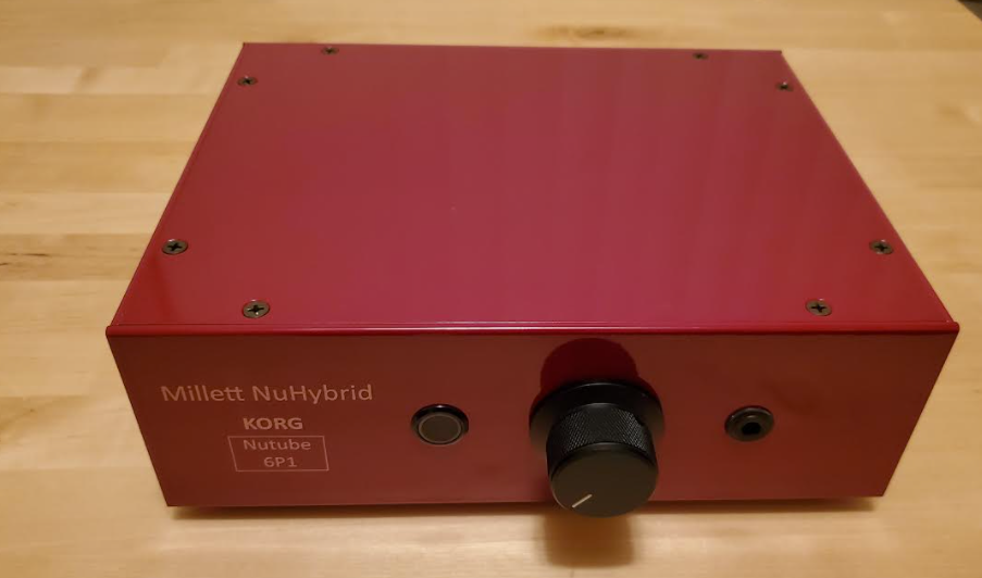
The gallery over at korgnutube.com has a stereo amp with the Nutubes mounted on small, seperate PCBs but I was thinking of a more ...errr "ghetto" sollution to putting the glow front/top and center on a Millett Nuhybrid.
Sure, you can do that. The pins are fragile so be careful. Or, you can buy a little PCB for $6: https://www.ebay.com/itm/Blank-Carr...735398?hash=item33d3eb2626:g:wN4AAOSw~epZf0B8
Pete
).

Yeah, that adds up!The carrier PCB has the pins duplicated on both edges of the board. So you only need to connect one side (e.g., JP3 and JP1).
Carrier=Amp [Nutube pin #]
P1=A1 [7], P2=A2 [10] (anode or plate)
G1=G1 [4], G2=G2 [14] (grid)
F1=F1 [1], F2=F3 [17] (these are the ends of the filament)
FC (either pin) = GND [8] and/or F2 [9] (these are connected together on the carrier and also on the amp, so you only need one wire)
So they all line up, except FC and GND/F2 (the tube has it in the middle, the carrier on the ends).
Hopefully that makes sense?
Pete

Hello. New guy here. Going for this as my first amp build!
First off, thanks to Pete for this and all the other builds he offers. It's great that he shares these designs, and I doubt this will be the only one I take on.
Second, thanks to all the people here. Having read through this thread, I have some ideas for my build, and I can tell this will be a good community to be a part of.
I just ordered the board and tube, and I have a few questions regarding deviating some of the BoM components before I order them. Most of it has to do with the electrolytic capacitors as many seem to customize their selections and one of the default ones is out of stock right now.
1. Can anyone verify how much room there is for the larger electrolytics? The default ones are out of stock, and I wanted to upgrade those as is. I see pictures where I believe people are fitting Ø16mm caps, but wonder if Ø18mm can be fit. This mainly applies to C3 and C6. I couldn't find the DXF files on Pete's site to measure everything.
2. Can anyone confirm that the Ø8mm Elna's listed as an upgrade on Pete's BoM fit without a lot of trouble? I'd like to upgrade to those, but those clusters look very tight.
3. I saw some people up-sized C3 and C6 to 1000uF, with tomb citing it for improving bass response I think. Is that the case, and does it have any undesirable effects on the rest of the range?
4. Should all the electrolytics be audio grade, or is it only important for the signal ones (C3, C6, C13, C14)? I was thinking of upgrading those 4 and changing the rest to endurance caps like Nichicon UPW or Panasonic FR since they're all decoupling the supply lines.
5. Having read some points about changing the values for R8 and R9, does anyone have any recommendations for their values? I will be using HD6XX's.
6. Any other tips, mods, or upgrades anyone is willing to recommend will be appreciated. I'm willing to spend a bit more to have some fun with this ($200 max for the package). I will be getting the TKD pot.
7. I'm planning to build a custom wood case when it warms up here (will be in the stock base until then). I'm thinking of something like a wood base with semi-open sides and a glass top. Anyone have wisdom or lessons learned to share with their enclosure building?
Thanks everyone. Looking forward to the build.
You can always install the capacitors from the bottom side of the board where you have plenty of room .
This is true, and I have considered mounting the adjacent film caps under the board to get the extra clearance, but I'd also prefer to keep the aesthetic of a fully populated board since I plan to keep it visible. I also don't want it to end up too tall, which under-mounting any of the electrolytics would do. My other concern is that the caps may be large enough to contact the solder points of the film caps, but I don't think Ø2mm would push it that far. Either way, I don't have a good way to measure it myself.
Hello. New guy here. Going for this as my first amp build!
First off, thanks to Pete for this and all the other builds he offers. It's great that he shares these designs, and I doubt this will be the only one I take on.
Second, thanks to all the people here. Having read through this thread, I have some ideas for my build, and I can tell this will be a good community to be a part of.
I just ordered the board and tube, and I have a few questions regarding deviating some of the BoM components before I order them. Most of it has to do with the electrolytic capacitors as many seem to customize their selections and one of the default ones is out of stock right now.
1. Can anyone verify how much room there is for the larger electrolytics? The default ones are out of stock, and I wanted to upgrade those as is. I see pictures where I believe people are fitting Ø16mm caps, but wonder if Ø18mm can be fit. This mainly applies to C3 and C6. I couldn't find the DXF files on Pete's site to measure everything.
2. Can anyone confirm that the Ø8mm Elna's listed as an upgrade on Pete's BoM fit without a lot of trouble? I'd like to upgrade to those, but those clusters look very tight.
3. I saw some people up-sized C3 and C6 to 1000uF, with tomb citing it for improving bass response I think. Is that the case, and does it have any undesirable effects on the rest of the range?
4. Should all the electrolytics be audio grade, or is it only important for the signal ones (C3, C6, C13, C14)? I was thinking of upgrading those 4 and changing the rest to endurance caps like Nichicon UPW or Panasonic FR since they're all decoupling the supply lines.
5. Having read some points about changing the values for R8 and R9, does anyone have any recommendations for their values? I will be using HD6XX's.
6. Any other tips, mods, or upgrades anyone is willing to recommend will be appreciated. I'm willing to spend a bit more to have some fun with this ($200 max for the package). I will be getting the TKD pot.
7. I'm planning to build a custom wood case when it warms up here (will be in the stock base until then). I'm thinking of something like a wood base with semi-open sides and a glass top. Anyone have wisdom or lessons learned to share with their enclosure building?
Thanks everyone. Looking forward to the build.
