


jobous
New Head-Fier
- Joined
- Feb 21, 2016
- Posts
- 14
- Likes
- 1
Beautiful !!! Nice work.

Thanks! I fricking love DIY.Beautiful !!! Nice work.


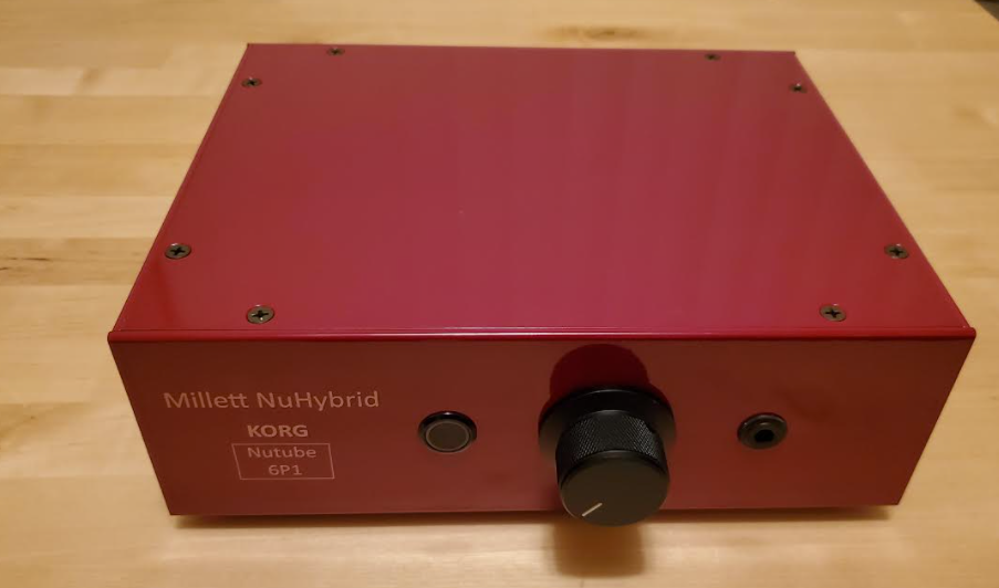
Brilliant write-up.Wrote up my build log with tips, tricks and info as an article for Headphonesty if anyone is interested. Designed to be a one stop shop for info.
If anyone thinks I missed anything important, just let me know!
My NuHybrid Headphone amp makes a noticeable pop in the headphones when switching off the power. Power up delay works fine. Loud enough to be alarming. Build is in a DIYaudio store Galaxy chassis with jacks and input pot (Alps RK27, 10K audio taper) off board.
Is this unusual? Any suggestions? Pardon if this has been covered previously, I'm new to the forum.
I'd like to share my mods to this headphone amp. I don't seem to have permission to add photos to this post, so here is a text only description:
NuHybrid Headphone Amp Mods
After building and listening to the Nelson Pass B1 Korg preamp and comparing it to the Pete Millett's Nutube Buffer preamp, I found I liked the sound of Nelson's Korg tube setup a bit better. I figured out how to make Pete's Buffer sound more like Nelson's B1 Korg and then it was onward to the NuHybrid headphone amp.
Not obvious is that all 3 circuit designs invert the signal. This happens at the NuTube itself. This is easy to correct with loudspeakers by reversing the loudspeaker/amplifier connection wiring but not easy with headphones unless you want to take them apart and rewire them. Listening tests confirmed that I preferred the correct polarity with loudspeakers, so I decided to add input transformers with reversed primaries to the NuHybrid to also correct that circuit.
I first experimented with some inexpensive Triad TY-250P transformers I had around just for evaluation purposes. Imaging was very much improved but their lack of shielding, excessive phase shift in the low bass and higher THD proved unacceptable. I ended up purchasing and installing a pair of Jensen JT-11P-1 1:1 high quality line input transformers and installing them with the primary winding connections reversed.
Here is what I did to modify the NuHybrid Headphone amp to compensate for the polarity inversion and to have it sound more like the Pass B1 Korg. The build was done in a DIYaudio Galaxy chassis with all jacks, power switch, LED and volume pot mounted off the PCB and on the chassis panels.
So how does it sound? With the resistor and plate voltage mods, I think it sounds better than the stock 475K plate resistors with voltage set closer to half-supply. Smoother, with no loss of dynamics or detail. Correcting the signal polarity with the transformers made a very significant improvement in detail and imaging. Yes, they cost as much as the PCB, tube and board components combined but once you hear the difference, there is no going back.
- The Jensen input leads are configured as unshielded twisted pairs connected directly to the isolated RCA input jacks. Input polarity is reversed with respect to the transformer output. The RCA jack shells (grounds) are tied together and connected to circuit ground to eliminate hum when a source is connected. The output leads of the transformers are configured as unshielded twisted pairs and connected directly to the volume pot inputs. The transformer can shields and internal electrostatic shields are connected to circuit ground at the input side of the board. I provided a direct chassis ground connection at that point a with the series resistor/cap to chassis ground connection shown in the Jensen data sheet. A dedicated ground wire was run from the volume pot ground terminals to circuit ground at the input side of the board. Since I was using a 10K pot, the Jensen data sheet damping network was not required. Even though my pot is an Alps RK27, it has excessive noise at the extreme CCW rotation, which seems to be a problem with 10K pots in general. If I end up changing it to something like a 50K, I'll add the recommended damping network.
- I bypassed the on-board PCB volume pot connections altogether and went straight from the pot to some slightly larger Kemet 220 nF input caps that were then connected to the PCB at the C20 and C21 locations. Shielded coax connections from the pot to the caps input sides are grounded only at the PCB end.
- I changed the NuTube plate resistors R13 and R14 to 332K.
- I set the plate voltage at TP1 and TP2 to about +9.75 volts. I found this is best adjusted while listening to music and set to your preference. I also found that anything over +10.5 volts made the magic go away.
