Millett Hybrid Build Log
Nov 28, 2006 at 2:10 AM Thread Starter Post #1 of 29

cgrums

100+ Head-Fier
Joined
Oct 27, 2006
Posts
246
Likes
10
Having just finished a

CMOY

DSC00557.jpg


DSC00558.jpg


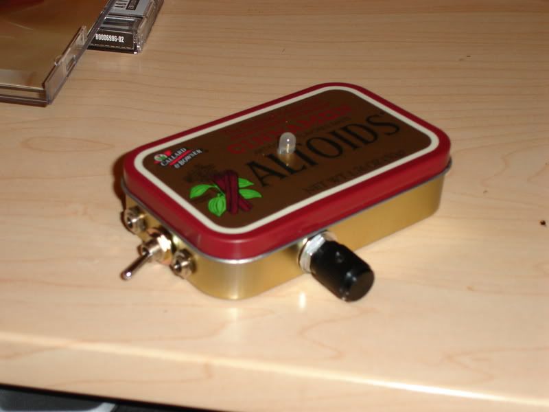
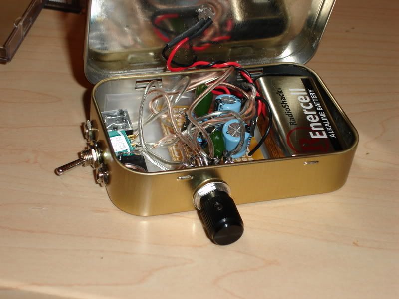
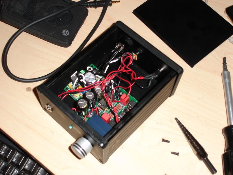
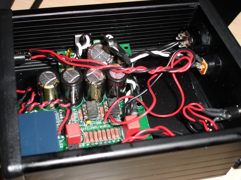
And a Pimeta with Panasonic FM caps, class A biasing, stacked buf634s and AD8620/8610 opamps. Thanks again to Tomb, Tangent and everyone else for answering all of my amateur questions
icon10.gif
(The current panel components are temporary hence the less-than perfect finishing):

DSC00573.jpg


DSC00577.jpg


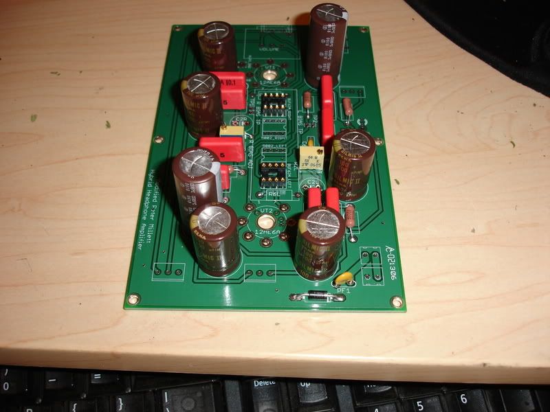
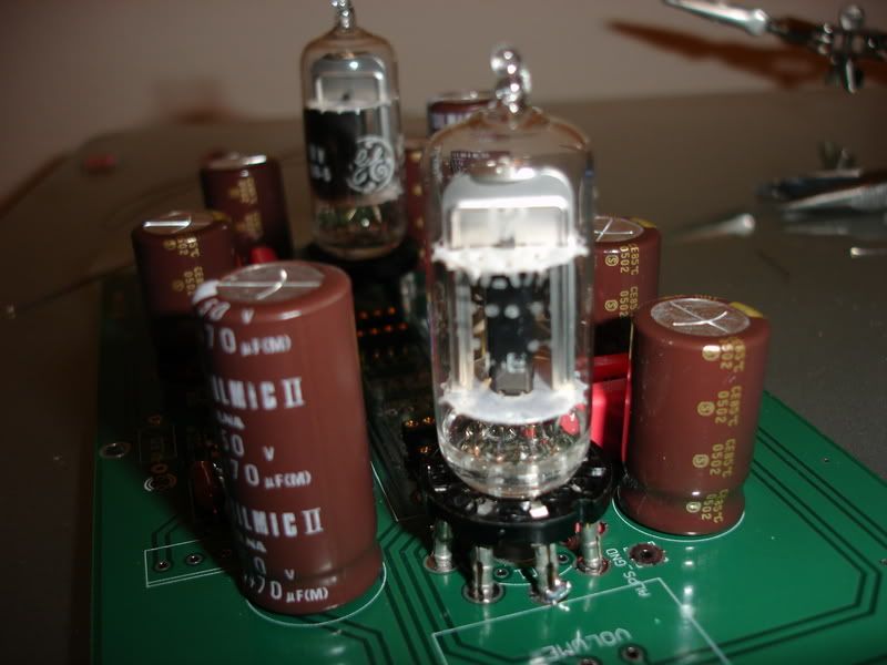
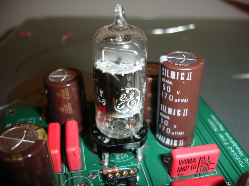
I have now started a new project:

DSC00582.jpg


DSC00585.jpg


DSC00583.jpg


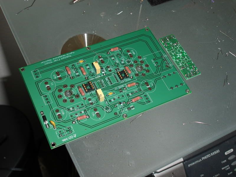
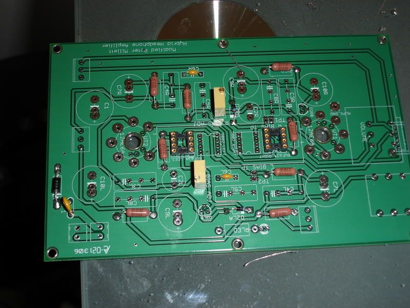
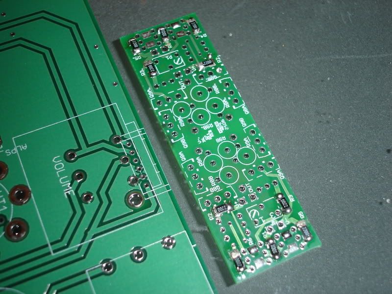
This is definitely my first foray into the world of smd (excluding the AD8620/10 onto browndog adaptors) and I think I'm getting the hang of it.

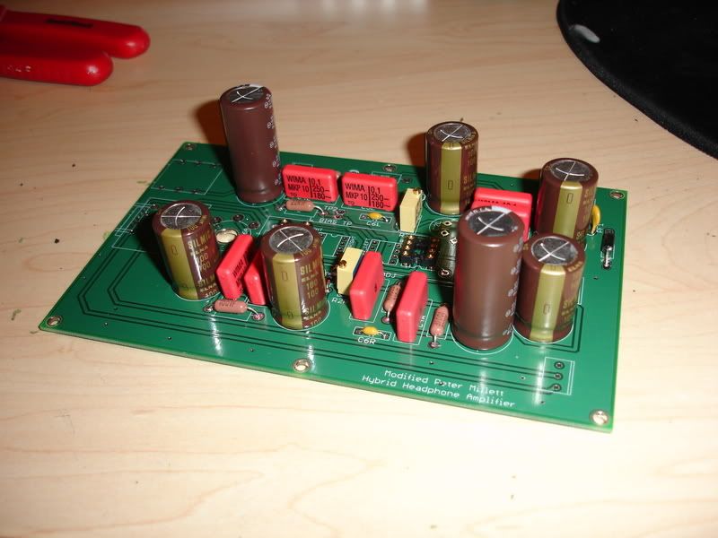
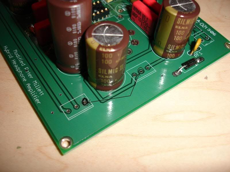
I have all the parts either here or enroute and am curious about capacitors. I'm planning to use BG standard on both C7 and C2 and Elna Silmic IIs on everything else. I've been reading a fair amount on not bypassing C7/C2 if using high enough quality caps and am fairly certain I want to leave the film caps unpopulated. It's clear to me from looking at the board that C4 is bypassing C7, is it C3 that bypasses C2? If it is then that should be unpopulated as well. Should I leave the rest of the box caps in?

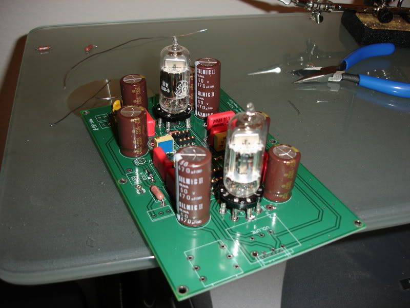
Another question: how important is transistor matching in the buffer? I'm reading different opinions and am kind of confused here. (I know I've seen a schematic for a simple circuit that is used to match the transistors so it shouldn't be that bad...right?)

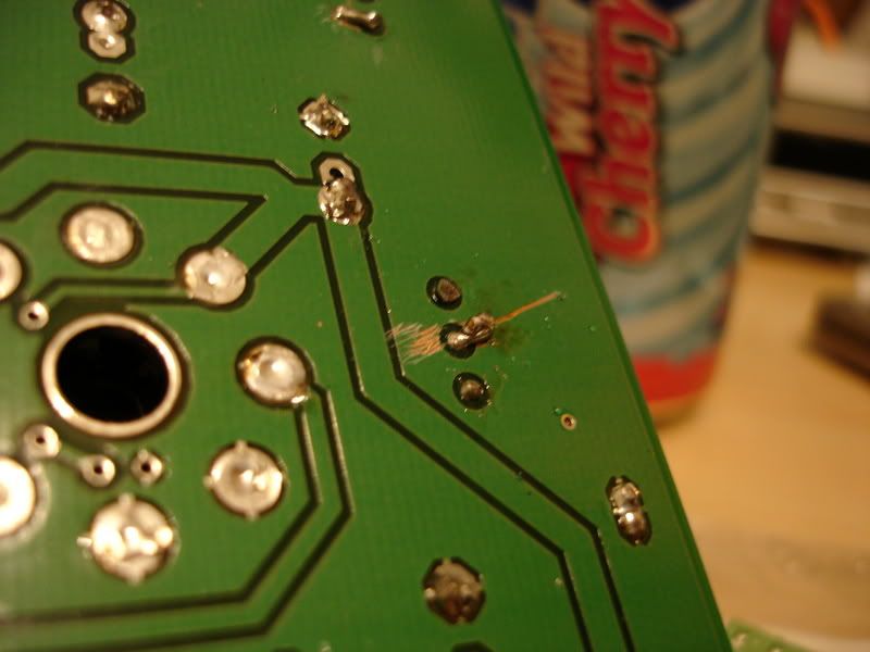
I'm hoping to document my Millett build better than my previous two to share my experience and hopefully get feedback before I screw anything up permanently.

Cheers
Cgrums
 
Nov 28, 2006 at 3:05 AM Post #3 of 29
Lookin' good so far! I haven't done the DB's yet myself, but I've read up on them. I believe all the trannies should be matched, but the big ones are not as critical - the pots take care of the rest. Steinchen's support site is pretty extensive, though - the answers are there or in the build thread on DIYForums.org.

Some obvservations:
- If you're going straight to the DB's, the resistors by the DIP-8 sockets are not needed. They won't hurt either way, though. They're the bandwidth-setting resistors for the BUF634's - 220ohms for singles, 110-100ohms for double-stacks.

- It appears that you have the boards with the grounding mistakes. Maybe we've already told you this. If not, here goes - the audio signal INPUT and OUTPUT ground pads are not connected to the board's ground. Vixr had the neatest solution for that if you're using the terminal blocks. Simply bend the ground lead underneath the board, scrape away some of the board exposing the copper ground plane underneath, and solder the pin to it. Works like a charm.

- You also have to be careful with the tube LED's or you'll burn one of them out or a resistor if you use the pads provided. Refer to the "Board Fixes" sticky on DIYForums for a photo showing the fixes by NeilR. Also, remember to use a RN60 resistor on the panel LED pads - it will see almost 3/4W of dissipation sized at 1Kohms (and 27VDC). A simple 1/4W carbon film or metal resistor may not be able to take it - even the big Vishay gets hot.

- Personally, I had no luck deleting the bypass caps. I wouldn't do it on the C2 cap anyway - boutique for the electrolytic for sure, but there's enough disagreement on that cap that you may get into more trouble by trying to delete the bypass film cap. Make sure you don't go bigger than the silkscreen image for C2 - otherwise your DB board will not fit.

C7 is definitely a boutique cap, but instead of enhancing the highs by deleting the film cap bypass, I lost all the bass response. Putting the film cap back in made it sound great. I was using Nichicon Muse ES's, supposedly known for good bass response. Yet, it didn't work for me. You are correct that C4 is the bypass cap for that position.

P.S. That PIMETA turned out well!
 
Nov 28, 2006 at 4:10 AM Post #4 of 29
Quote:

Originally Posted by tomb /img/forum/go_quote.gif
- It appears that you have the boards with the grounding mistakes. Maybe we've already told you this. If not, here goes - the audio signal INPUT and OUTPUT ground pads are not connected to the board's ground. Vixr had the neatest solution for that if you're using the terminal blocks. Simply bend the ground lead underneath the board, scrape away some of the board exposing the copper ground plane underneath, and solder the pin to it. Works like a charm.


Which board are you referring to? The DB? Thanks.
 
Nov 28, 2006 at 4:43 AM Post #5 of 29
Quote:

Originally Posted by cgrums /img/forum/go_quote.gif
Which board are you referring to? The DB? Thanks.


He is referring to the main board. The input ground (third one from the top) is not connected to the ground plane. Also output ground at the output bethween c1 and c10l is not connected to the ground plane. And the output on the right of Rled is also not connected to the ground plane.
 
Nov 29, 2006 at 3:48 AM Post #6 of 29
Made a little more progress...

DSC00586.jpg


Didn't want to wait any longer on the Blackgates so I went with the Silmic IIs all around.

DSC00588.jpg


So I think I understand the whole grounding thing. It's these two locations that need to have ~1/8" of substrate scraped away in order to solder the coresponding pins of the terminal blocks: (forgive the terrible MS Paint)

markedup.jpg


And since I'm going to be using the leds under the tubes I'll not need to worry about the rled trace not being grounded...correct?
 
Nov 30, 2006 at 5:00 AM Post #7 of 29
More parts in this evening. Got the tube sockets in and decided to take care of the terminals for the input/output at the same time.

DSC00592.jpg


DSC00593.jpg


DSC00594.jpg


I'm fairly certain I took care of the input/output terminal grounding issue but ran into one snag: I got a little carried away with the razor and scraped into the trace as can be seen in this picture:

DSC00597.jpg


I decided to bend the terminal pin to the opposite side, am I going to have a problem here?
 
Nov 30, 2006 at 6:17 AM Post #8 of 29
You're looking good so far on most things - you're probably excited to get this done. The Millett is worth the effort. Those Silmic's look nice - I think I will try them on the new Millett Hybrid Max.

As for specifics:
I can't tell what's going on in that last pic. If you didn't bend the lead toward where you scraped off the coating, you haven't made a connection. Also, there's only one set of input pads - in the back where you've identified. However, there are two sets of output pads and a separate set of1/4" jack Neutrik pads, making 3 potential output pad sets - you only use which is most convenient for you. The Neutrik pads are not messed up. If you plan on using that jack, you don't have to mess with any output pads, period. If you don't use the Neutrik pads, the closest output pads are the ones near the front of the board by the LED pad (RLED). That one has to have the Ground fixed.

There was never anything wrong with the RLED pad. It's the tube LED pads that are messed up. One set connects the LED directly to 24V. I tried being cute and just sizing a larger resistor once, but it didn't work - the second tube light just got dimmer and the larger resistor got scary hot. That's because the tubes are connected in series and depend on equal loading to balance the voltages between channels (single-ended design). Better to connect the LED leads to the originally-intended point in the circuit.

Did you go find that posting that showed how to correct the problems? That would've made all this clear - the bent tab was just a different method to address the same circuit problems identified in that Sticky on DIYForums.org:
Millet Boards: New Revs Fixes and Tweaks
 
Nov 30, 2006 at 11:49 AM Post #9 of 29
I don't have any problems with the millett resistor pads under the sockets.. I usually use a 1k and 2k resistor (1k for the 12V, 2k for the 24v), and no major heat issues. The 24V resistor will get warm to the touch, but it's still touchable. I do use a 1/2 watt carbon film resistors, though.
 
Nov 30, 2006 at 12:45 PM Post #11 of 29
I think you may run into problems with those tube sockets further down the road. The insertion/removal of tubes is going to place stress on the socket and it looks like the only mechanical connection to the board is through solder. If you do a lot of tube rolling, I'd imagine those joints are going to break down over time.
 
Nov 30, 2006 at 5:06 PM Post #12 of 29
Quote:

Originally Posted by tomb /img/forum/go_quote.gif
As for specifics:
I can't tell what's going on in that last pic. If you didn't bend the lead toward where you scraped off the coating, you haven't made a connection. Also, there's only one set of input pads - in the back where you've identified. However, there are two sets of output pads and a separate set of1/4" jack Neutrik pads, making 3 potential output pad sets - you only use which is most convenient for you. The Neutrik pads are not messed up. If you plan on using that jack, you don't have to mess with any output pads, period. If you don't use the Neutrik pads, the closest output pads are the ones near the front of the board by the LED pad (RLED). That one has to have the Ground fixed.


Thanks Tomb, I did read the fixes on diyforums.org and believe I've taken care of everything that needs to be...the last picture there is refering to the fact that I ended up scraping across that trace beneath the hole for the terminal pin. Is that going to be a problem? I've got the pin for the terminal bent to the opposite side and soldered so the connection has been made...I'm just curious about the scraping extending across that trace.
 
Dec 6, 2006 at 6:06 AM Post #14 of 29
Got home from work to a package from handmade electronics containing, among other things, my Nichicon Muse 220 uf caps to fill c2. Got everything wired up, applied 24 volts with the tread, adjusted the right bias just fine....can't get anything to change with the left, regardless of numbers of turns of the trimpot. I'm thinking maybe a bad pot? Bad connections with the tube? What else should I check?
 
Dec 6, 2006 at 12:25 PM Post #15 of 29
Quote:

Originally Posted by cgrums /img/forum/go_quote.gif
Got home from work to a package from handmade electronics containing, among other things, my Nichicon Muse 220 uf caps to fill c2. Got everything wired up, applied 24 volts with the tread, adjusted the right bias just fine....can't get anything to change with the left, regardless of numbers of turns of the trimpot. I'm thinking maybe a bad pot? Bad connections with the tube? What else should I check?


I've just about given up suggesting this, seems like no one else has had this trouble. With me, it happened to every one of my 4 Milletts in some degree or other: check the tube sockets/tube pins. All it may take is a little tube wiggling to get the bias voltage to register. Connect your multimeter up so that you can watch the bias voltage on one of the tubes. Wiggle it and see if the voltage drops below your TREAD's supply voltage (by more than 1 or 2 volts). If so, then slightly bend the pin pairs together that correspond to the bias connection (pin 7? I can't remember). Try to bend them slightly out or to the sides in line with the pin circle. It depends on how the socket is loose.

As I said, maybe it was just me, but almost every one of my sockets gave me fits (ceramic PCB). Moreover, if the one near the Pot is loose, the entire second tube won't conduct due to the single-ended design. Thankfully, a slight bending of the pins is all that it takes. Long-term, you might try popping the tops of the socket off and squeezing the socket tabs together slightly with a pair of pliers. If they're glued, you may be able to get an Xacto blade in there to separate the halves.

BTW, you might try 27V with the TREAD - that's the standard most use. It was confirmed in Amb's tests, too, as the voltage that gave the best all-around results. That would be 13.5V on the bias for each tube.
 

Users who are viewing this thread

Back
Top