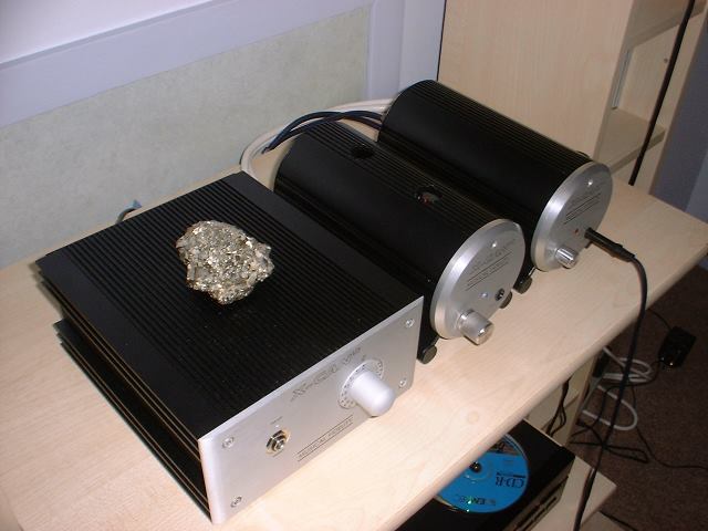
I must have a case of X-Can fever at the moment as I've only gone and bought yet another one! So I now have an X-can V3 and two V2's when really I only need
one of these amps.... X-Can V2 number 3 was a total impulse buy and I think I must be going mad buying these amps as if they're going out of fashion.
Anyway, I bought another one and have just finished tarting it up with (even though I say it myself) amazing results.... this is the best sounding V2 to date by quite some margin.
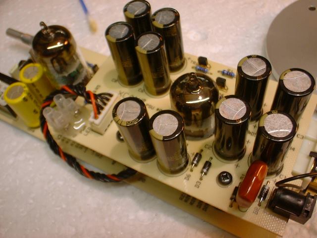
I managed to source some of the Panasonic FM series of capacitors for this V2 and decided to fit 35V 1200uF caps across the PSU board. They "just" fit inside the enclosure and are pretty much the perfect size for the V2.
Also decided to remove the 50K generic potentiometer and replace it with a 10K dual log ALPS pot from
RS components (part number 249-9159) this is
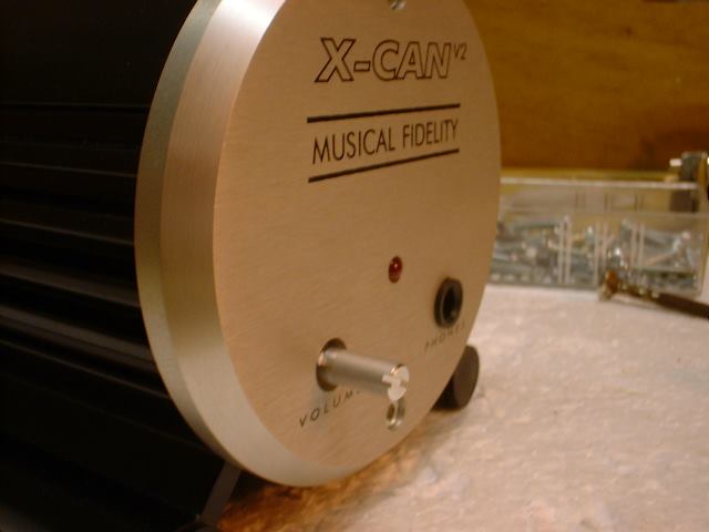
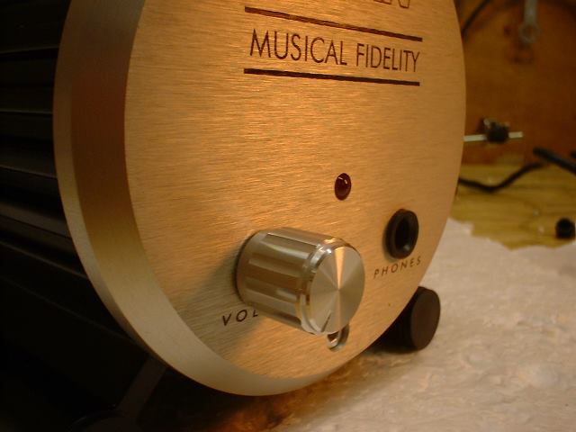
far superior sounding to the stock 50K pot and the longer shaft means you can fit on a cool knob of your choice....... I went with the 15mm fluted aluminium knob from
RS components (part number 498-889) and it looks very dinky indeed
On the bottom board I replaced the 4 x 35V 100uF electrolytics with 4 x 50V 120uF Panasonic FM. I replaced the 2 x 50V 10uF polar electrolytic input caps with 2 x 50V 10uF Non Polar "SamWha" caps and replaced the 2 x 6.3V 220uF nonpolar output caps with 2 x 35V 470uF non polar "Nitai" caps. Replacing the 10uF input caps with non polars and upping the output capacitance from 220uF per channel to 470uF per channel brings about major improvements to the bass and overall clarity..... you really have to try it to believe just what a big improvement changing these caps brings about.
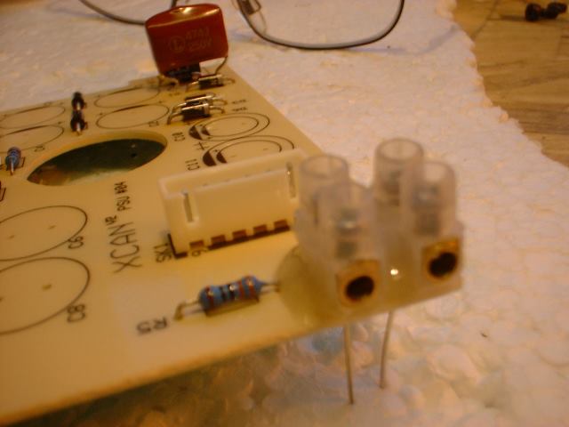
I also soldered a couple of wires into a connector block and glued the block to the PSU board...... this makes it easier to remove the LED if you're under the bonnet quite a lot.
Enough of my waffling here is the recipe for you to try..... trust me, this tastes GOOD!
Ingredients:
10 x Panasonic FM 35V 1200uF (RS part number: 526-1777)
4x Pansonic FM 50V 120uF (RS part number: 526-1610)
2 x Nitai 35V 470uF non polar capacitors (RS part number: 768-598)
2 x SamWha 50V 10uF non polar capacitors (Nitai will do fine)
1 x 9mm 10K dual log ALPS potentiometer (RS part number 249-9159)
Note: I've bypassed the 10uF input caps and 470uF output caps with 220nF film caps. I left all of the Panasonic FM's as they are to preserve the very low ESR.
Method:
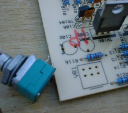
Let's start by removing the 50K potentiometer:
The pads are very small so be very careful when you are desoldering and don't leave the iron on too long or the pads will lift...... use a desolder pump and some braid to remove the solder and the pot will pull clear of the board pretty easily.
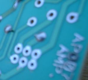
Pot removed and ready for new pot to be soldered into position.
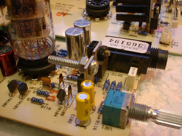
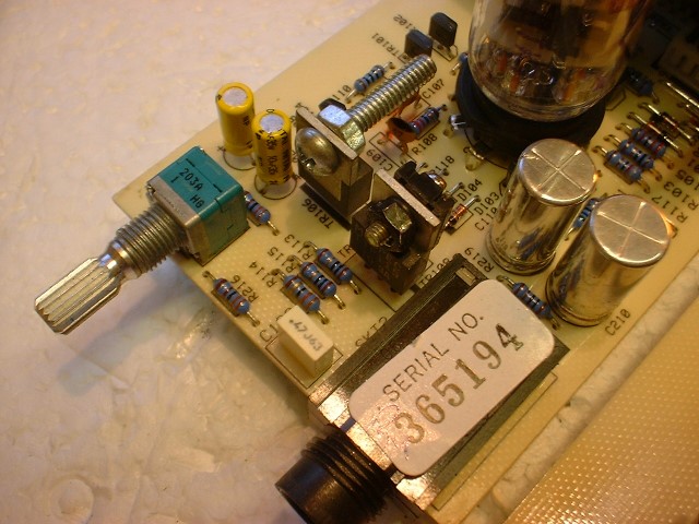
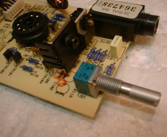
New 10K ALPS pot in position.
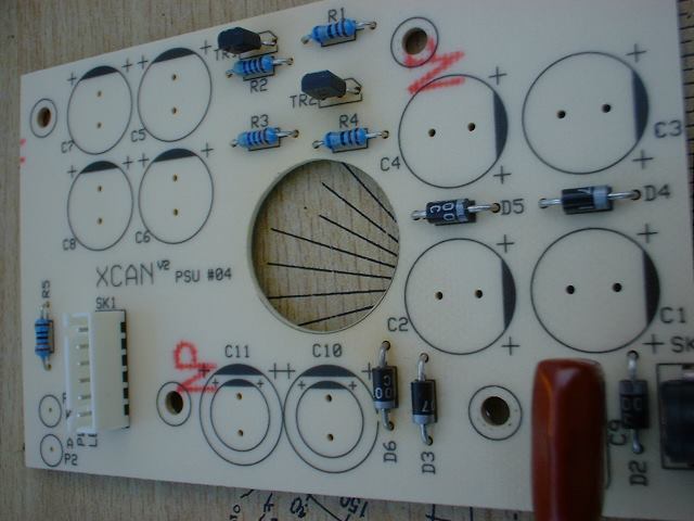
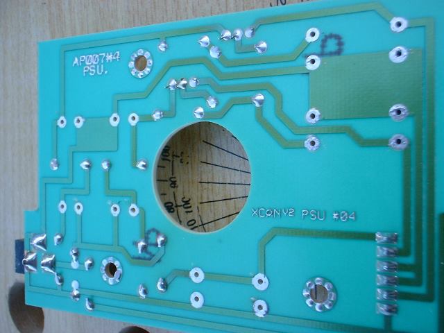
Right, that's that done. Now we'll remove all of the electrolytic capacitors from the PSU board:
Capacitors removed from PSU board. The best method here is to grab a capacitor and pull it upward whilst applying heat to the pad.... do this a couple of times on each pad and the cap will pull out of the board easily. Mop up excess solder from the pads with soldamop (desoldering braid)
Caps removed and pads cleaned with soldamop ready to accept new capacitors.
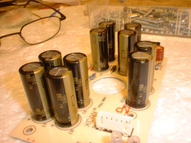
OK, now grab the 10 x 1200uF Panasonic FM caps and fit them to the board. Remember to fit them the correct way round.... the board is clearly marked with "+" so the long leg of the capacitor goes to "+" and the shorter leg (side that has a stripe on it) goes to -
There we go..... that's the PSU board completed with 10 x Panasonic FM in position.
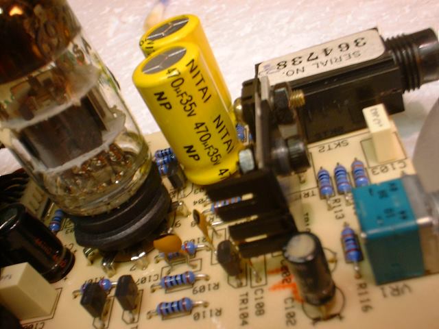
Next, remove the 2 x 220uF output caps and replace with 2 x 470uF non polars....... I have chosen "35V" here deliberately as the bigger the case size the better and you
can hear a difference between 6.3V and 35V types. Feel free to bypass these two caps with small value film caps if you like.
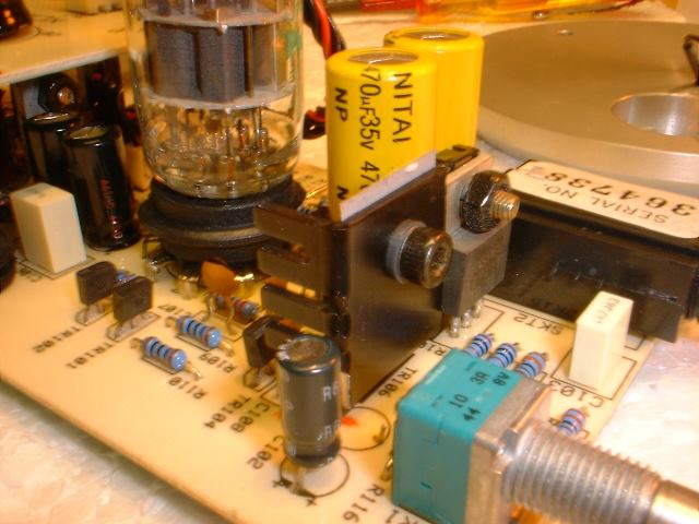
2 x 470uF Nitai Non polar caps in position.
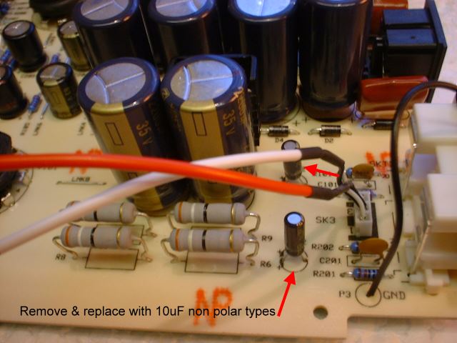
Next replace the 10uF "polar" input caps with 10uF non polar types and, again. bypass with film caps if you like:
Only 1 x 10uF non polar showing as I fitted the other one underneath the board.
Fit the 4 x 120uF into position and that's it
A few more pics:
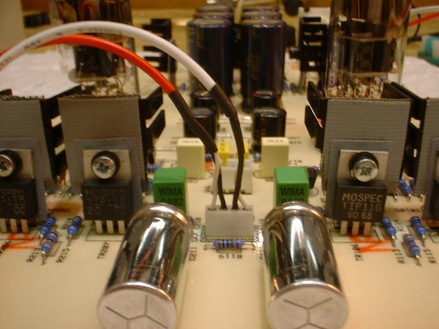
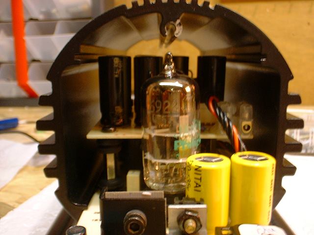
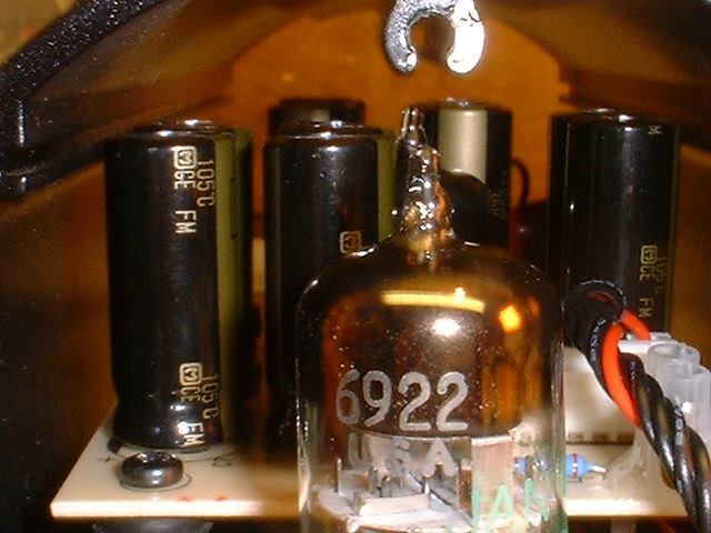
The 1200uF Panasonic FM's are a good tight fit.
They just clear the sides of the enclosure and no more.
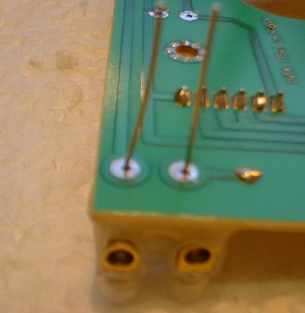
My little contraption for the LED connections
LED connector contraption waiting to be soldered.
Plenty of shaft on the ALPS 10K pot for a nice little knob
New knob in place.
Overhead view.
These really are effective tweaks and they totally transform the V2 from good to astonishing sounding IMO....... give them a try it only costs a few quid (about £18)
Someone stop me please!