PinkFloyd
Headphoneus Supremus
- Joined
- Jan 13, 2009
- Posts
- 9,511
- Likes
- 31
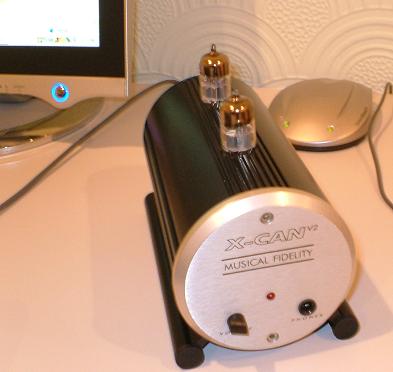
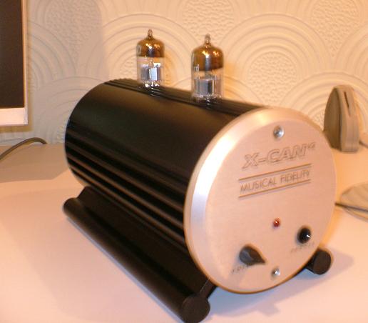
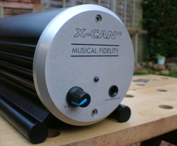
I couldn't live without my X-Can V2 so have recently bought another one and am in the process of tarting her up a bit. Anyone else here got one and, if so, any tweaks you want to share? If so this is the place to do it

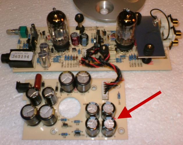
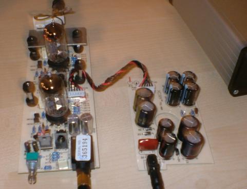
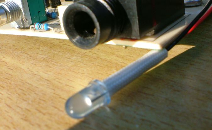
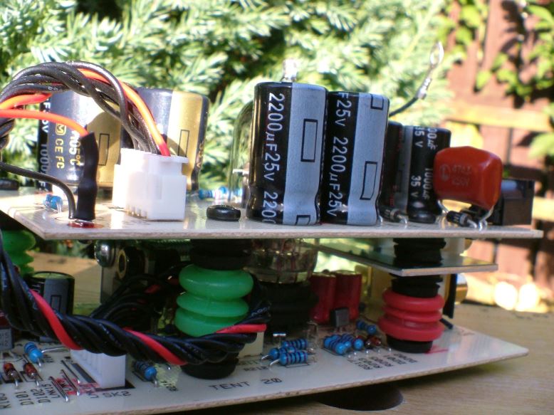
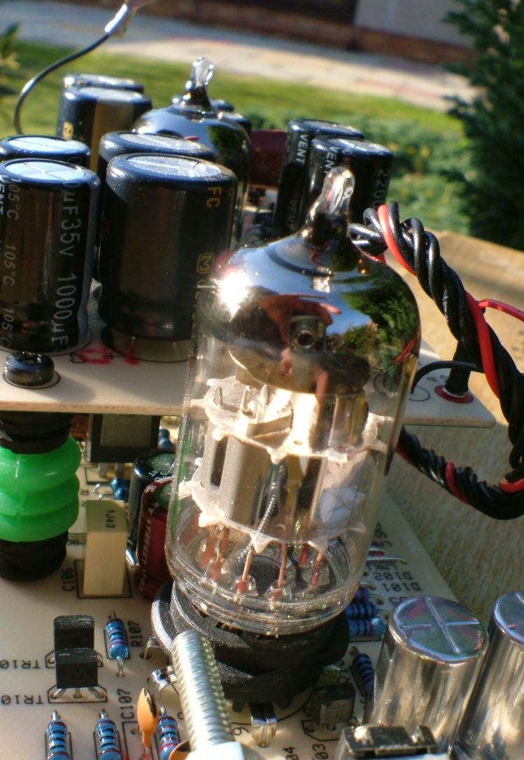
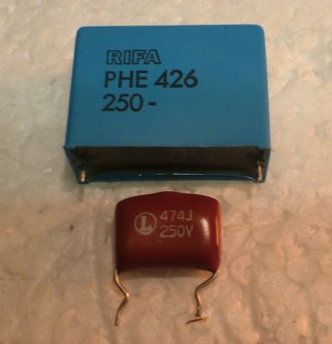
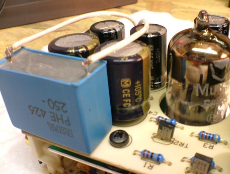
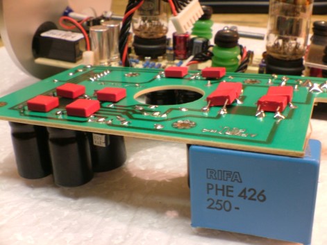
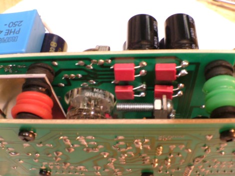
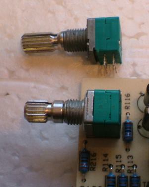
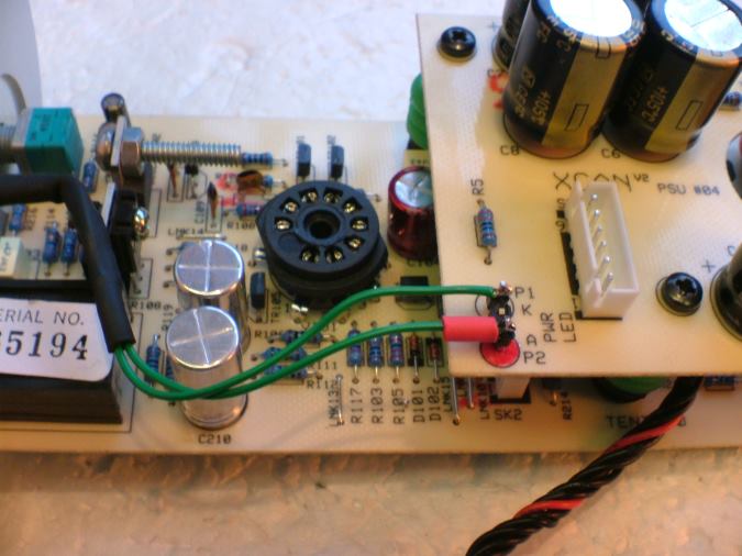
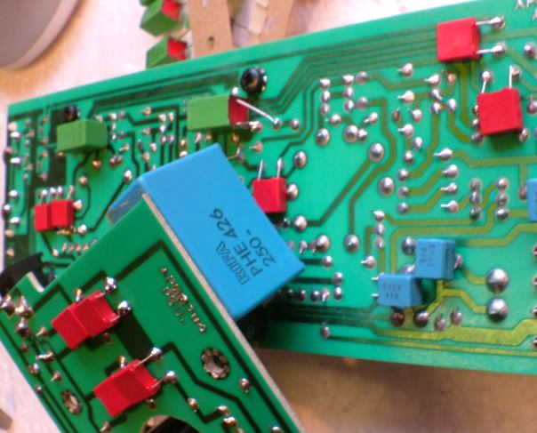
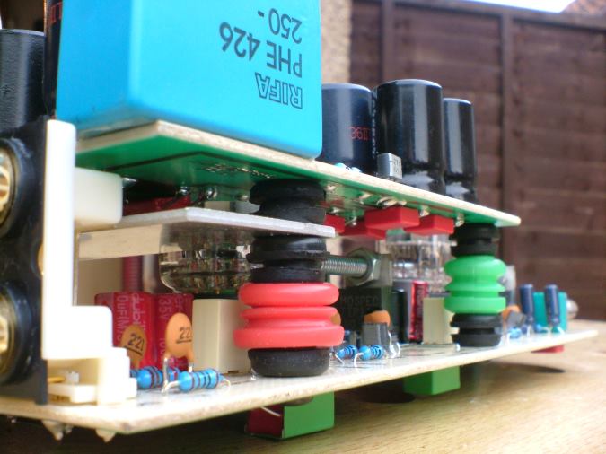
I posted quite a fair bit in another thread so will move it all over here and make this a dedicated X-Can V2 thread. The few bits and bobs I've done really have transformed the V2 from a decent sounding amp into something of a high end sounding beast and all it takes is the odd capacitor here and there.. seriously, the difference is night and day.
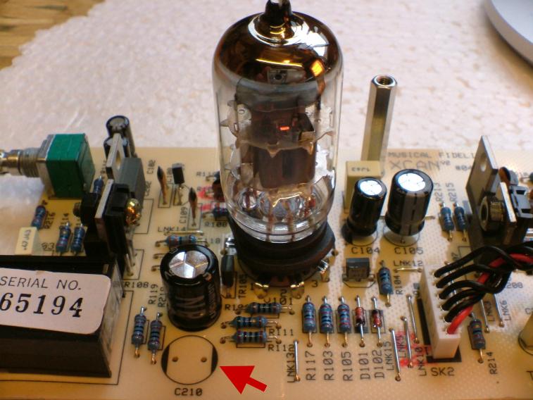
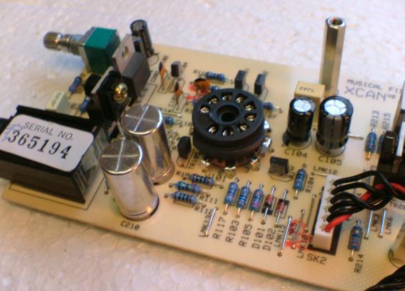
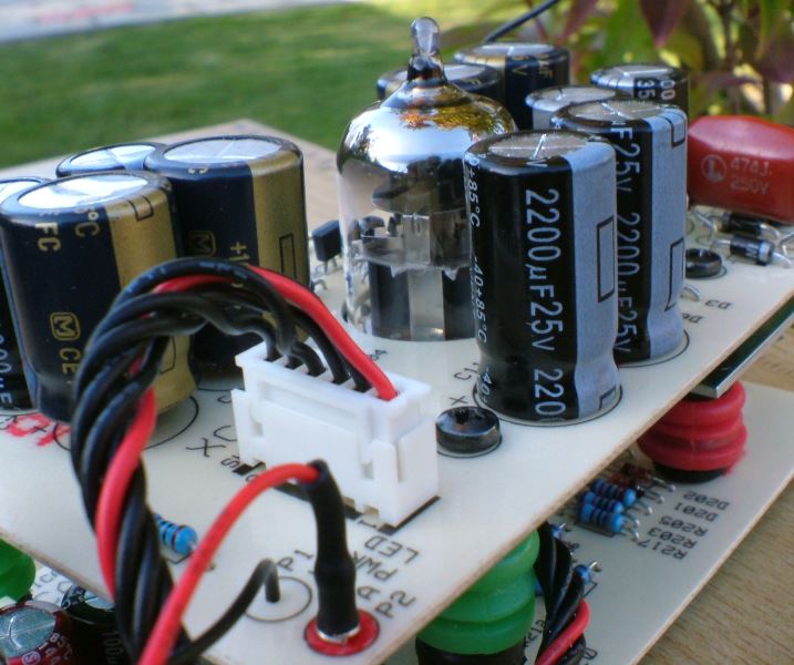
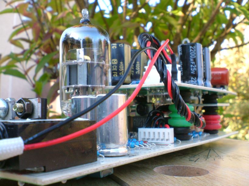
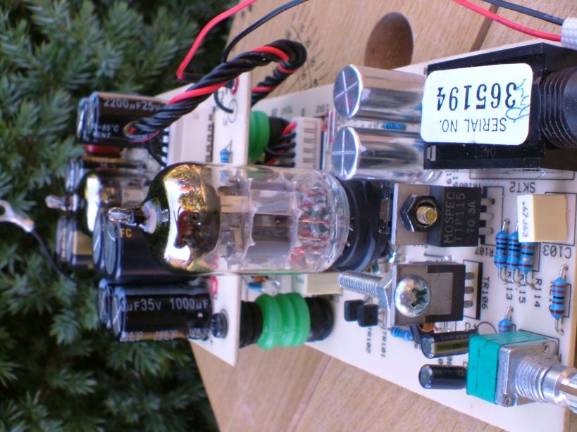
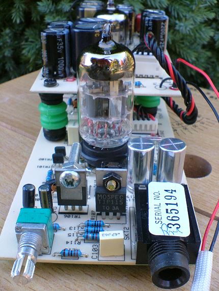
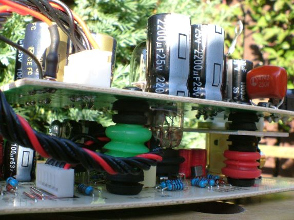
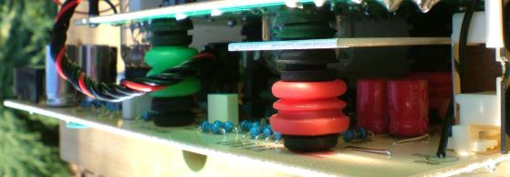
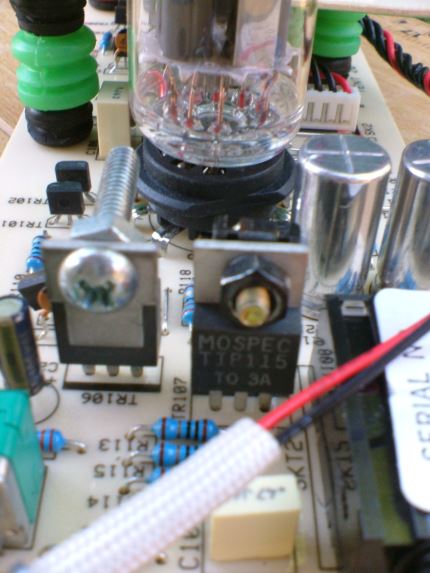
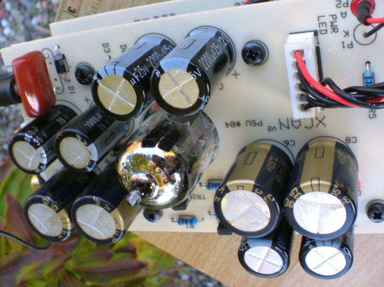
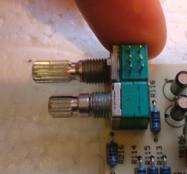
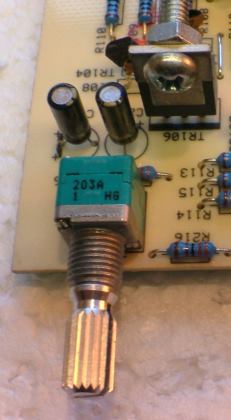
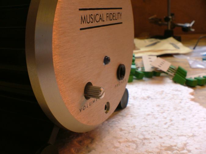
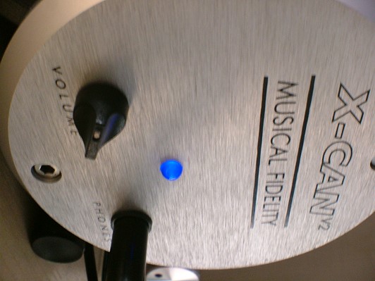
Well, here's where I'm up to with mine..... if you've got any good tweaks please share them here
I posted quite a fair bit in another thread so will move it all over here and make this a dedicated X-Can V2 thread. The few bits and bobs I've done really have transformed the V2 from a decent sounding amp into something of a high end sounding beast and all it takes is the odd capacitor here and there.. seriously, the difference is night and day.
Well, here's where I'm up to with mine..... if you've got any good tweaks please share them here