MF X-Can V2 tweaks
Oct 19, 2005 at 8:18 PM Thread Starter Post #1 of 71

PinkFloyd

Headphoneus Supremus
Joined
Jan 13, 2009
Posts
9,511
Likes
32
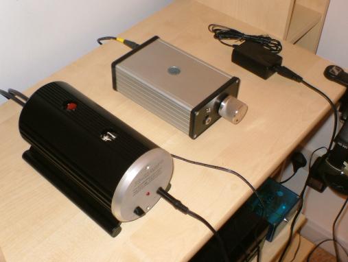
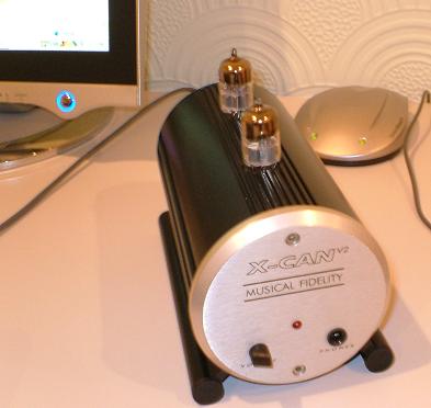
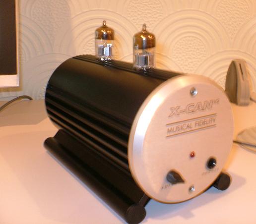
I couldn't live without my X-Can V2 so have recently bought another one and am in the process of tarting her up a bit. Anyone else here got one and, if so, any tweaks you want to share? If so this is the place to do it
smily_headphones1.gif


3.jpg


I posted quite a fair bit in another thread so will move it all over here and make this a dedicated X-Can V2 thread. The few bits and bobs I've done really have transformed the V2 from a decent sounding amp into something of a high end sounding beast and all it takes is the odd capacitor here and there.. seriously, the difference is night and day.

Well, here's where I'm up to with mine..... if you've got any good tweaks please share them here
smily_headphones1.gif
 
Oct 19, 2005 at 8:21 PM Post #2 of 71
.
Quote:

Originally Posted by PinkFloyd
I just got hold of another X-Can V2 yesterday and have already started playing about with it
biggrin.gif
Just couldn't help myself as I had a few bits and bobs going to waste...... It's work in progress but so far this evening I've replaced the 6.3V 220uF non polar output caps with 6.3V 1000uF varieties bypassed with Evox polypropylene caps. Fitting higher capacitance output caps sure does make the bass go a lot deeper..... I'll probably get around to removing the output caps all together but for now 1000uF makes a big improvement.

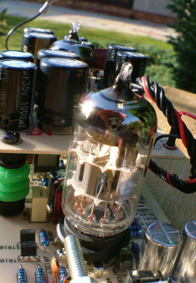
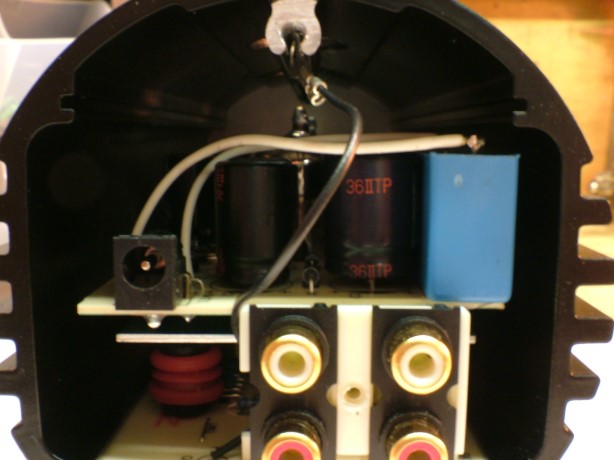
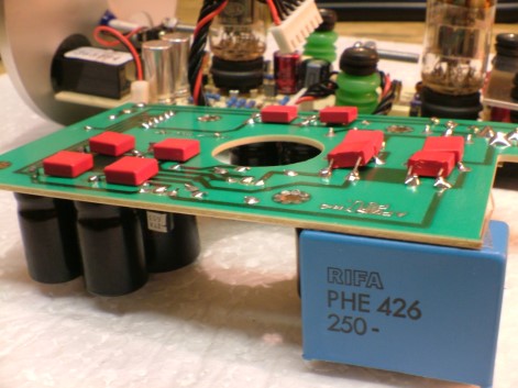
Also started fitting more capacitance onto the PSU board (upper board) this is the part of the X-can where fitting more capacitance reaps major improvements. There are 8 x 1000uF and 2 X 470uF as stock....... these can safely be replaced with much higher capacitance.... MF suggest replacing them all with 2200uF (if fitted in the X-Can enclosure) or the sky is the limit if fitting the boards into a larger enclosure. I only had a few caps to hand but have replaced 4 of the 1000uF with 1600uF and the two 470uF with 1000uF... the other 4 x 1000uF I'll replace with 2200uF once I get hold of some.

Swapped out some of the Jamicon caps for Nichicon fine gold and ELNA stargets in key areas and will also get around to bypassing them with film caps at some stage. Also fitted some rubber grommets to the stand offs to provide damping and will be rolling Mullards in once I've completed the rest of the mods this weekend.

The results so far? In a word......Outstanding. Bags more weight and delivery and oodles of warm luscious (yet very tight) bass, night and day over the stock V2 for sure. Changing the capacitors for another brand always reaps results in the V2 but increasing the capacitance brings about quite awesome improvements as does upping the output caps capacitance and fitting bypass caps..... I'm tempted (very tempted) to go absolutely mad with capacitance on the PSU board but that would mean either fitting an offboard cap bank or housing the V2 in a much larger enclosure and I'm not sure I'd want to do either as I like the aesthetics of the V2.

I'll upload everything to my website when the project is complete (probably next week sometime) I'm awaiting a replacement pot, caps, 0.1% resistors, some transistors and a few other bits and bobs.... in the meantime I'm just absolutely immersed in the music and am really really enjoying the music with this X-can!!

7.jpg

Removed the two 220uF non polar output caps

3.jpg

Replaced with 2 x 1000uF non polars

1.jpg

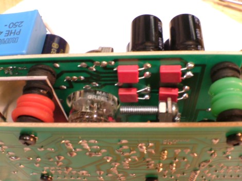
Bypassed the 1000uF non polars with polypropylene film caps on underside of board

5.jpg

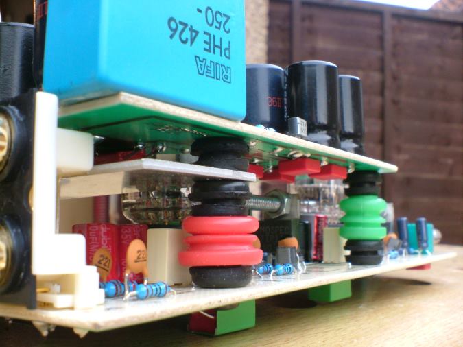
Fitted rubber dampening grommets to stand offs
6.jpg


8.jpg

These caps are still to be removed and replaced with 2200uF varieties

4.jpg

Enjoying the music!


Oct 19, 2005 at 8:22 PM Post #3 of 71
.
Quote:

Originally Posted by PinkFloyd
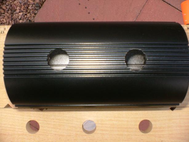
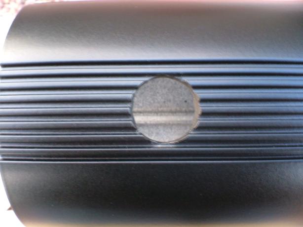
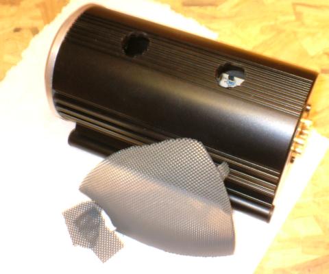
Still awaiting some parts so this evening was spent cutting out a couple of ventilation holes... well, not so much ventilation holes more like chimneys directly above the valves allowing the heat to escape through the holes...... will get around to fitting mesh as soon as some epoxy arrives
smily_headphones1.gif


hole1.jpg

Holes cut and primed ready for paint.

hole2.jpg

Close up of hole (looks a lot better in reality)

hole4.jpg


mesh.jpg

Dark Grey mesh ready to be cut and fixed into position.

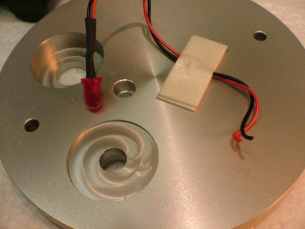
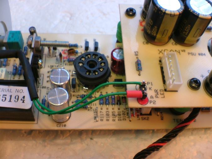
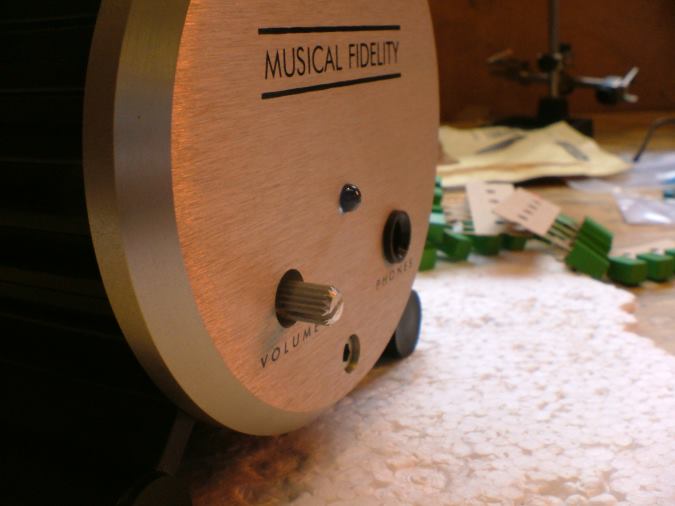
I also "popped" the red LED out of the fascia ready to fit a 5mm diffused blue LED.

led1.jpg

Led popped out of hole

It may be of interest that the resistor directly above the red arrow is in series with the LED so this is the one to change if you're thinking about fitting a blue LED. The stock red LED uses a 330R resistor in this position and I guesstimate that swapping this for a 5K resistor would be ideal for a blue LED:

8.jpg


She's starting to take shape and should be finished on Saturday if the parts arrive tomorrow
smily_headphones1.gif


Oct 19, 2005 at 8:23 PM Post #4 of 71
.
Quote:

Originally Posted by PinkFloyd
Instead of the mesh maybe something along the lines of this........

valve.jpg


valve2.jpg


Doable and would make valve rolling a breeze
smily_headphones1.gif


Oct 19, 2005 at 8:24 PM Post #5 of 71
.
Quote:

Originally Posted by PinkFloyd
Got a bit more done today. Finished off the holes with a second coat of semi sheen black and decided against fitting wire mesh inside the holes.... Instead, i'm going to get hold of some rubber grommets to bung into the holes when it's switched off.

Fitted the blue LED and hooked in a 4K resistor in series with the anode to give a really muted light. I left the 330R resistor on the board.

f.jpg


Swapped out the stock 500mA wallwart for a 1000mA wart from Rapid and it's a lot better than the 500mA (more weight and clarity) and it's only a fiver (£5). It also comes with a 2.1mm DC plug fitted so it's a direct plug in alternative to the stock PSU. Probably get round to building a PSU but for the time being the 1000mA is far better than the stock wart.

Fitted some capacitance to the PSU board (a few 2200uF here and there) and, for sure, the more you fit the better the sound, in particular the bass..... I'm taking notes and plenty of pics so will put up a few pages on each of the tweaks once i'm happy with them.

Next up is replacing the potentiometer and fitting high quality phono sockets etc.

A few more pics of a true British classic:

1.jpg

Red LED replaced with blue.

3.jpg


4.jpg

Holes finished.

6.jpg

Capacitance beefed up with el cheapo guinea pig caps

7.jpg


8.jpg


9.jpg


a.jpg


b.jpg

Funky stand off dampers. (grommets!)

c.jpg


e.jpg


g.jpg


DSCF1615.jpg


EDIT: Just rolled in the Mullard E88CC's....... whoah!!


Oct 19, 2005 at 8:25 PM Post #6 of 71
.
Quote:

Originally Posted by PinkFloyd
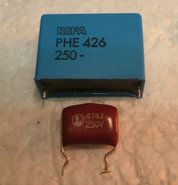
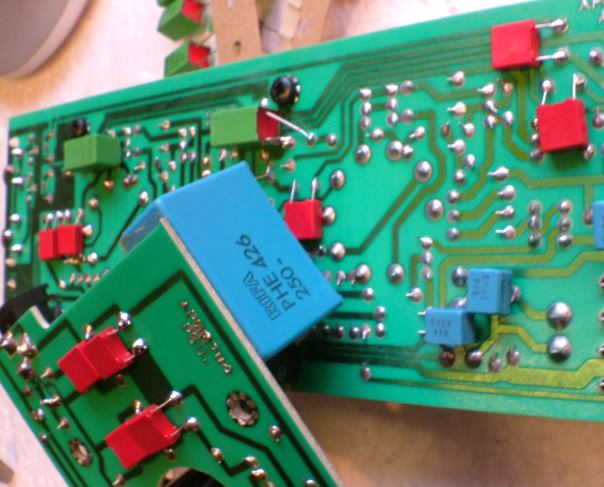
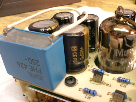
This puppy responds favourably to every little change you make to it...... I swapped the 470nF polyester film cap for a 250V 4u7 RIFA polypropylene and also bypassed all of the electrolytics with film caps (shunt capacitors soldered in parallel with the electrolytics) ....... wham! improvements across the board... bass, clarity, dynamics, you name it!

I'll upload all of these tweaks once I've tidied the amp up... in the meantime if you've got a V2 cram as much capacitance into that can as you can, it really makes a huge improvement.

This modification in conjunction with the increase in capacitance is extremely worthwhile. Many commercial amps don't use the best capacitors in their signal paths or don't include shunts on their decoupling capacitors. Also Anthony Michaelson (MF) doesn't believe that caps make any sonic difference and that shunts are a waste of money (he mentioned this in an interview a few years ago). His philosophy is evident in all MF products whether it be the X-can or their flagship gear.... they are all crammed with cheap and cheerful Jamicon general purpose caps and, in the case of the V2, capacitance has been compromised in order that the amp can fit inside the can! (just ask the tech guy at MF he would fit FARADS of capacitance in if cost and size were no object
wink.gif
) .

This all means that even their most expensive amps can be easily improved for a very modest cost
smily_headphones1.gif


DSCF1756.jpg

Get rid of that orange 470nF cap and fit something bigger
cool.gif


DSCF1751.jpg

There's just enough room inside for it!

DSCF1735.jpg

Fixed to the PSU board using double sided sellotape.

DSCF1726.jpg

Electrolytics bypassed with film caps.

DSCF1744.jpg


Oct 19, 2005 at 8:57 PM Post #7 of 71
Got to work on replacing the potentiometer and bypassed a few more electrolytics with film caps this evening. Yet again, the V2 responds to every little tweak and it sounds better than ever!

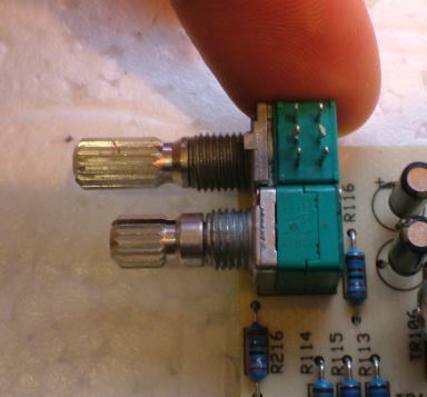
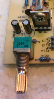
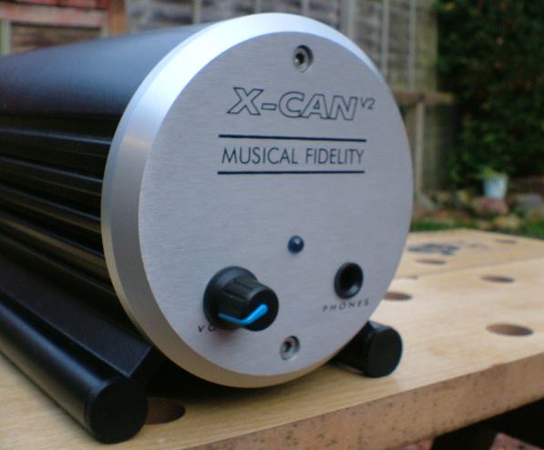
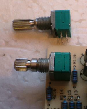
The stock potentiometer is a 50K dual log type. It is not an ALPS pot, as previously indicated, it's a cheap noname ALPS lookalike. I replaced it with a genuine ALPS 20K dual log type with a longer splined shaft so I could fit a different knob on, the shaft on the stock pot will only accommodate the tiny little black knob MF supply with the amp and, as anyone will tell you, it's far from ideal.

Desoldering the existing pot is pretty easy if you arm yourself with a desoldering pump and some good quality soldamop. I selected the best pot I had (out of three) and the tracking is pretty much spot on... a LOT better than the stock 50K pot for sure
smily_headphones1.gif
More clarity to the sound (probably due to the 50K to 20K change) and better channel tracking..... well worth doing.

DSCF1757.jpg

ALPS lookalike waiting to be removed from PCB.

DSCF1758.jpg

Genuine ALPS 20K replacement has a longer shaft.

DSCF1767.jpg

Replacement ALPS pot in place.

DSCF1783.jpg


DSCF1781.jpg

More shaft to fit a different knob onto.

[size=medium] See knob poll for some pics of alternative knobs for the V2[/size]

DSCF1794.jpg


[size=medium]More bypassing:[/size]

If you got them flaunt them...... "them" being film caps! The V2 seriously loves film caps and this is one area where the biggest improvements can be gained. It's an ongoing process with me but, so far, I've bypassed all of the electrolytics with one film cap each (some polyester, some polypropylene) Eventually each electrolytic will be bypassed with three film caps each... comprising a polypropelyne, a polyester and a silvered mica.... It'll be a very tight squeeze but well worth it I'd imagine.... not too sure about values maybe 1uF polyester, 100nF polypropylene and something like 100pF silvered mica.... one thing is for sure bypassing the electrolytics with film caps works wonders
cool.gif


DSCF1772.jpg

bypass caps.... (untidy) work in progress

DSCF1775.jpg

Room for some more but not much!

To be continued........
 
Oct 19, 2005 at 9:41 PM Post #9 of 71
Quote:

Originally Posted by PinkFloyd
I couldn't live without my X-Can V2 so have recently bought another one and am in the process of tarting her up a bit. Anyone else here got one and, if so, any tweaks you want to share? If so this is the place to do it
smily_headphones1.gif


3.jpg


I posted quite a fair bit in another thread so will move it all over here and make this a dedicated X-Can V2 thread. The few bits and bobs I've done really have transformed the V2 from a decent sounding amp into something of a high end sounding beast and all it takes is the odd capacitor here and there.. seriously, the difference is night and day.

Well, here's where I'm up to with mine..... if you've got any good tweaks please share them here
smily_headphones1.gif


Well, I purchased my X-CAN V2 while living in Spain, but now I live in the US. So the first mod is a new wall-wart style power supply. It'll use a 30 VA toroid transformer, and a DC blocking filter.

BTW, your website sites a DC power connector 9.5mm in length. The original cable is terminated with a plug that is 11.2mm in length.

Second step will be to trace out the circuitry. From there, I can make some decisions on what to fiddle with next. I'm guessing that the X-CAN uses some sort of boost converter to power the valves from 12 Vac. I'll bet there's a fair amount of ripple, if done cheaply.

Do you have the Alps P/N you used?

Thanks,

Rob
 
Oct 19, 2005 at 10:31 PM Post #10 of 71
Quote:

Originally Posted by weinstro
Well, I purchased my X-CAN V2 while living in Spain, but now I live in the US. So the first mod is a new wall-wart style power supply. It'll use a 30 VA toroid transformer, and a DC blocking filter.


Yeh, the 500mA stock wallwart can run a bit hot... 30VA is a lot better for sure
smily_headphones1.gif


Quote:

Originally Posted by weinstro
BTW, your website sites a DC power connector 9.5mm in length. The original cable is terminated with a plug that is 11.2mm in length.


9.525mm to be precise. The 11.2mm power plug that is fitted on the end of the MF wallwart doesn't need to be that long...... 9.5mm is a much better fit.


Quote:

Originally Posted by weinstro
Do you have the Alps P/N you used?


Not that particular pot, no. The guy who very kindly sent me them is on holiday but I'll ask him for the P/N when he returns.

There is another version that doesn't have the splined shaft and also the shaft is longer @ 25mm (STRK09707) 10K log.

I'll find out the part number for the 20K splined shaft version and get back to you.
 
Oct 20, 2005 at 5:52 AM Post #11 of 71
Quote:

Originally Posted by PinkFloyd
Yeh, the 500mA stock wallwart can run a bit hot... 30VA is a lot better for sure
smily_headphones1.gif


I have a question regarding the input voltage:

Is it 12 Vac RMS, zero-peak, or peak-peak?

Thanks and regards,

Rob
 
Oct 20, 2005 at 3:14 PM Post #12 of 71
Wow, great pics. That pot and knob are huge improvements. How long did it take to swap out the pot?

All this is making me want to buy the x-can v2 I can get my hands on. I hope it's still available.
 
Oct 20, 2005 at 6:07 PM Post #13 of 71
Quote:

Originally Posted by PinkFloyd
Not that particular pot, no. The guy who very kindly sent me them is on holiday but I'll ask him for the P/N when he returns.

There is another version that doesn't have the splined shaft and also the shaft is longer @ 25mm (STRK09707) 10K log.

I'll find out the part number for the 20K splined shaft version and get back to you.


I was planning on getting the one you mentioned but I can't seem to find it here in the states (tried Mouser & DigiKey)
frown.gif
I might just try soldering the nub I sawed off of my ALPS Blue on to the end. I have a black steel knurled knob from a local guitar shop to use. I'll post a pic tonight.
 
Oct 20, 2005 at 9:38 PM Post #14 of 71
Quote:

Originally Posted by weinstro
I have a question regarding the input voltage:

Is it 12 Vac RMS, zero-peak, or peak-peak?


I really don't know Rob but would assume it was the root-mean-square value
confused.gif
All it says in their specs is "12V AC 500mA mains adaptor"

EDIT: are you referring to the input ripple?

Quote:

Originally Posted by The Monkey
How long did it take to swap out the pot?


About 2 minutes to desolder it and around a minute to solder the new one on.

Quote:

Originally Posted by Juergen
I'll post a pic tonight.


Cool
smily_headphones1.gif
I'll find out the part number of the pot as soon as my friend returns from his holiday.
 
Oct 21, 2005 at 2:11 AM Post #15 of 71
Here's my potential replacement....


knob.jpg


You mention that the cap upgrades greatly improve the stock V2 but those Mullards do alot also (so I have heard). I replaced my stock valves with the Sovtek 6922s. They were really inexpensive. I can't seem to find Mullards for less than $100 US a pair. I might power up my V2 tonight. I haven't listened to it in about a year
eek.gif
 

Users who are viewing this thread
Back
Top