"Maxing out" a PPAv2?
May 12, 2007 at 5:12 AM Thread Starter Post #1 of 16

peppergrower

New Head-Fier
Joined
Feb 23, 2007
Posts
6
Likes
0
Right now I'm very interested in building a PPAv2, and I've spent quite a bit of time on tangent's site looking over his suggestions. I've also poked through the archives, and a lot of people talk about a "maxed out" PPA. What kinds of things does this usually involve, e.g. what do you do differently from a standard PPAv2? And what does this usually bump the cost of parts up to?
 
May 12, 2007 at 5:21 AM Post #2 of 16
it's very subjective.

IMO, a maxed out PPA v2 consists of Full vishay dale resistors, perfectly matched vishay siliconix buffer transistors (within a hfe difference of 3 or 2), heatsinked output transistors, dyn-o-bias II with matched CRDs, Silmic IIs for power caps and reservoirs, AD829 configured with compensation pin as output, STEPS PSU will all the goodies, ALPS RK027, etc. (you can really add up alot of other pricy stuffs LOL)

Yes, this is my so called "maxed out PPA v2" in my opinion.
 
May 12, 2007 at 7:15 AM Post #3 of 16
For some reason the term "maxxed out" within PPA vernacular is very liberal. I would consider "maxxed out" to consist of boutique caps in the signal path, a STEPS power supply and Diamond Buffers, or otherwise known as discrete outputs. I'd also like to see a bass boost on it.
 
May 12, 2007 at 8:06 AM Post #4 of 16
Quote:

Originally Posted by khbaur330162 /img/forum/go_quote.gif
I would consider "maxxed out" to consist of boutique caps in the signal path, a STEPS power supply and Diamond Buffers, or otherwise known as discrete outputs.


But the PPAv2 has diamond buffers by default and there are no caps in the signal path and just about everyone uses a STEPS anyway so that would make all PPAv2s maxed out
rolleyes.gif
And IMO maxing out a PPAv2 is just populating the board fully with quality parts plus at least a STEPS and maybe a stepped attenuator for volume control.
 
May 13, 2007 at 4:58 AM Post #5 of 16
It's nice to have some suggestions. I'm trying to strike a balance between cost and quality on this one, so I know I'm not sticking in high-end everything. It seems like these are some good suggestions, though, so I'll see how much I can fit in within my budget. I'll have to go with a lesser power supply for now, but I plan on upgrading later. The planning stage is fun.
 
May 13, 2007 at 10:05 AM Post #6 of 16
The further you bias the opamps etc into class A the less complicated power supply you will need as the circuits peak current draw will be closer to the normal current draw so the circuit will be closer to a resistive load.
 
May 13, 2007 at 1:05 PM Post #7 of 16
Quote:

Originally Posted by peppergrower /img/forum/go_quote.gif
It's nice to have some suggestions. I'm trying to strike a balance between cost and quality on this one, so I know I'm not sticking in high-end everything. It seems like these are some good suggestions, though, so I'll see how much I can fit in within my budget. I'll have to go with a lesser power supply for now, but I plan on upgrading later. The planning stage is fun.


I agree with Epicurean in general, although a stepped attenuator has not been in my budget and may never be.
wink.gif
Many of us have trouble finding better caps than the Panasonic FM's if you are out of the signal path, which is the case for all of the electrolytics. Certainly, Vishay-Dale resistors are advisable, and careful attention to matching transistors is helpful.

As for the Class A bias, the PPA is biased to 30ma, I believe, but can't go higher due to the lack of heat sinks. This is more than sufficient for most headphones, though, unless you're really interested in a MAXimum effort.
very_evil_smiley.gif


The STEPS is definitely warranted. However, a lower cost alternative may be Amb's new Sigma11. It can be powered by a walwart, which cuts the build cost considerably, I would think.
 
May 13, 2007 at 2:31 PM Post #8 of 16
Quote:

Originally Posted by tomb /img/forum/go_quote.gif
The STEPS is definitely warranted. However, a lower cost alternative may be Amb's new Sigma11. It can be powered by a walwart, which cuts the build cost considerably, I would think.


Tom, I'm not sure the sigma11 is less expensive than the STEPS. If I had to hazzard a guess after building a few of both I'd say that if anything the sigma11 might be just a touch more expensive to build although I haven't done a strict comparison line item by line item. There's also something to be said for the adjustability and all in one nature of the STEPS.

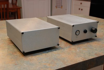
As far as what qualifies as a maxed PPA, I'd agree with most of what's been said. Boutique caps, carefully matched components, premium opamps, exotica internal wiring and a high quality power supply. My own version of the story was this amp:

medium.jpg


medium.jpg
 
May 13, 2007 at 10:51 PM Post #9 of 16
personally, I disagree about the STEPS power supply and would consider the matching battery board to be considered maxed out. Granted, mine doesn't really have much of a battery life (depending on the opamps and bias setting, currently I'm using 30mA and OPA627/637), but it's sufficient for a decent listening session and sounds absolutely fantastic. I use an Elpac for charging the battery board and I have both the battery board, PPAv2 and the cross feed in a single Hammond case.
 
May 13, 2007 at 11:17 PM Post #10 of 16
Quote:

Originally Posted by n_maher /img/forum/go_quote.gif
Tom, I'm not sure the sigma11 is less expensive than the STEPS. If I had to hazzard a guess after building a few of both I'd say that if anything the sigma11 might be just a touch more expensive to build although I haven't done a strict comparison line item by line item. There's also something to be said for the adjustability and all in one nature of the STEPS.


Hmm ... that's interesting. It looks like you built yours similar to a STEPS, sort of - toroid and all. I was just thinking that if you simply populated the board in a minimum enclosure and used an AC walwart ($6?) that it would be cheaper.

EDIT: Sorry, I guess that's a redundant comment on my part.
 
May 14, 2007 at 7:28 AM Post #11 of 16
I am building a PPAv2 now, the most challenging part is to get the 2088/5087 Hfe matched in Q23/Q33 (I buy 50 each, and get them matched within 10%), and it's also impossible to match hfe of Q24/Q34.
I also use a sigGen to feed in 1K signal and try to match the left/right channels on the output. To nulling the DC offset (8ma in my case) also require some effort. (luckly, my OPA627/637aus come with offset trim pin). If you buy the mil-spec OPAMP (like OPA637BP), your won't have that much trouble.

If you really want, try to hand match all the resistor's value down to 0.1%.
use Jung's super regulator may give you better spec on PSU. for me, i stick with STEPS.

I think a maxed PPA doesn't means it comes with expensive parts, A carefully tweaked PPA is what you should after.
 
May 14, 2007 at 8:28 AM Post #12 of 16
Quote:

Originally Posted by hellomai /img/forum/go_quote.gif
I am building a PPAv2 now, the most challenging part is to get the 2088/5087 Hfe matched in Q23/Q33 (I buy 50 each, and get them matched within 10%)


I bought 30 of each, matched them with the hfe meter of my 10$ DMM and got 1-2mV offset on first try so I wouldn't really say it was challening. But maybe I was just very lucky.

Quote:

and it's also impossible to match hfe of Q24/Q34.


How so? The difference here is that you should run the same current through them when measuring them as when they are in the circuit, which is probably 30mA.
 
May 14, 2007 at 2:14 PM Post #14 of 16
about the no op-amp mod, anyone here has high offset when the volume exceeds 60% and above? It's just a very weird problem, below 60%, the offsets is around 1-5mV, once it exceeds 60% the offset suddenly rises to about 30mV. Power supply voltage is 24V.
 
May 15, 2007 at 5:23 PM Post #15 of 16
Quote:

Originally Posted by Epicurean /img/forum/go_quote.gif
How so? The difference here is that you should run the same current through them when measuring them as when they are in the circuit, which is probably 30mV.


I thought you should match the Hfe for the output Q24/Q34, look here on note3.
 

Users who are viewing this thread

Back
Top