Low battery indicator circuits
Sep 11, 2004 at 2:01 AM Post #46 of 68
tangent-hadron-9v-lowbatt2.png


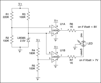
This is very similar to hadron's second circuit, but with one of the dividers in a different position to make the arithmetci easier, and using the band-gap reference instead of a zener. I built it, and it works beautifully.

Simply set the dividers equal to 2.5 divided by the desired trip point. My values are for 7 and 8V, so the dividers are set to 0.357 and 0.3125, respectively.

I'll be building your circuit next, aos.
 
Sep 11, 2004 at 3:23 AM Post #47 of 68
I built your most recent circuit aos, and tested it with a variable bench supply. There seems to be no gap either way: no point where both LEDs are on, no point where neither is on.

It takes the same number of resistors and LEDs as the hadron/tangent circuit, so the only part difference between the two is the active parts. The aos parts cost about 1/2 that of the hadron/tangent parts, the two probably take roughly the same board space, and the aos circuit has a small edge in current consumption. The resistor values in the two schematics above won't give equal brightness, but this still applies after correcting for that.

The only advantage remaining to the hadron/tangent circuit is the three-state feature.

aos, I don't understand what you mean by "double the circuit and remove the third transistor".

I also don't understand how you knew the voltage across the TL431 would go to ~1.9V when it begins conducting in this configuration. No circuit in the datasheets I've seen shows this trick, and I don't see an explanation in the datasheet that explains it. Do you just have to study the TL431 internal schematic to know this?
 
Sep 11, 2004 at 10:01 PM Post #48 of 68
What I meant is, you can make two circuits like this, which nets you total of 4 LEDs. You can then set each to different threshold. In one of them keep only the first transistor/LED combination in each (the other one is just an inverter on top of the first one). This LED will be active when the voltage drops below certain level; let's set it to level where you want the LED to be "orange" (i.e.to the red part of the tri-pin bicolour LED). Then make
another, full circuit, except that you can replace the first LED with a
resistor and just keep the second one. Tie this one to green LED and let the
threshold of this circuit to be so that it extinguishes when you want
the LED to be "red". That way you need 1 1/2 circuits to achieve
three colour state. The cost is a bit larger size and extra 1mA of consumption. One benefit though is that the builder doesn't have
to populate the extra parts on the board if all he/she wants is a
two-state light, and also you could actually go for two separate
LEDs, blue one for good power, and bi-colour orange(red+green)-red
for the low battery indication (you'd need two full circuits for that).

Since TL431 is TO-92 and so are other two transistors, wouldn't it take less space than a DIP-8 chip and a TO-92 reference? You can opt for vertical
mounting of resistors to make it smaller - drawbacks of vertical mount
shouldn't be of concern in a circuit like this.
 
Feb 16, 2005 at 10:45 PM Post #49 of 68
IMO, this is a lot of expense and work for a simple LED. Better to put time and construction costs into the amp itself? I mean, it's neat and would make the whole-amp better but portables are big enough already?

I'm in favor of KISS. Based on LED v-drop, use resistor that will shut it off when voltage gets too low. Sure, it will consume a few (couple?) more mA at full battery voltage (unless you like to run batteries down to nothing and hear the clipping, but then all these added components will consume a couple mA too, right?

On the other hand, what I'd find more useful is if the amp turned OFF when voltage got too low, like if left on and unattended. Can than be accomplished simply by putting a zener + transistor in series on, to break the power input?

Edit: Not to be misconstrued, I think the work being done by Tangent et al is great. Educational, inspiring, and if you don't cut it out my office will look like radio shack before long!
 
Mar 26, 2005 at 11:08 PM Post #50 of 68
And...I would be really interested if u would take the time and explain it in detail..I'm sure there are more people than me interested in this..
smily_headphones1.gif

Works great with a distinct turn-over between led's, which I prefer, it all depends on where u decide to let the "red" led lit doesn't it? (a third color isn't that all important)

/Peder
 
Jan 26, 2011 at 2:11 AM Post #53 of 68
i'm all for discrete cct's for stuff, but there are all manner of chips from Ti and linear tech that do all of this and much more. one from linear in particular LTC2953
 that includes a momentary driver, LED driver, fuel gauge and voltage monitor. uses a resistor network to sense voltage and at a level of your choosing will trigger a response, be it a warning LED, logic level signal to an MCU for house cleaning, or initiate low current operation etc, then at the second low level it will trigger a shutdown which can be pirated to pull the regulators low and latch until battery goes over the set level again. all sort of possibilities. I prefer the linear stuff as I love their LDO's and this works very well with them. pretty low power consumption too. for all this it requires fairly minimal parts count also, probably less than above
 
Jan 26, 2011 at 9:58 AM Post #54 of 68
Thanks for your idea qusp. I checked around and it appears this chip is only available in SMD 12-pin, $5. 14uA current draw is attractive, however. I'm the one who asked aos to repost his circuit...thanks again!  I'm trying to shoehorn a bicolor circuit into the scrathpad of the Pimeta V2 board, which is spaced for through-hole components. Browndog has an apadter for $6 but in the end I think I'll do the simpler Tangent/Hadron or aos path. If some more ambitious person takes a crack at it, I'm all ears, however. As it is I'll be doing some 2-1 Y soldering in the air to make it work.
 
Collin
 
Quote:

 
Jan 27, 2011 at 4:46 AM Post #55 of 68
You pretty much need to design a circuit board for that, though. You also have to order the chip from the supplier. While you could just hack the analog circuit as well as buy parts in your local electronics store. And it is probably cheaper, too. I agree though, if I was designing something I'd probably use the chip like you mentioned. But if you are building somebody else's design it's much easier to add a small perfboard with a simple analog circuit than open Eagle, spend an hour in it and then wait 3 weeks for the boards to arrive (at high cost)...
 
Jan 28, 2011 at 2:45 PM Post #58 of 68
Jan 28, 2011 at 2:48 PM Post #59 of 68
Thanks for posting aos's design with additional notes.  I'd like to ask something. I had bought previously the parts required for Tangent/Hadron's circuit, and he's listing resistor values in excess of 100k.  Since I was going to use that circuit I'm resulting in R1 and R4 values of 470k and 511k (if R2 is 100k). Pretty high values and I'm concerned these will introduce needless noise to the Pimeta's power supply.  Aside from more current draw, is there any reason I can't tone those down to values more like those shown in aos'? 
 
Collin
 
Jan 28, 2011 at 3:43 PM Post #60 of 68
Here is a little board I drew up for the circuit.
1 inch square. I'm sure it could be smaller if
you tombstone the resistors.


Users who are viewing this thread

Back
Top