Little Dot Tube Amps: Vacuum Tube Rolling Guide
Sep 21, 2013 at 11:17 PM Post #3,017 of 13,434
One of the two 6AH6WA's glows quite a bit brighter than the other one and I don't notice any difference in sound.
Upon examining the tubes it appears that the brighter one's filament stick's up a little above the mica making it look brighter.
 
Any unforeseen problems with this? Or nothing to worry about?

Sorry for the bad phone shot.
Thanks!
 
Sep 21, 2013 at 11:23 PM Post #3,018 of 13,434
Meine Switchen's have arrived... I am going to install these in the back panel of my LD to allow for easy strapping changes. (While powered off of course.)


I'll get circuit board pictures with this install.
beerchug.gif

 
Sep 21, 2013 at 11:28 PM Post #3,019 of 13,434
  One of the two 6AH6WA's glows quite a bit brighter than the other one and I don't notice any difference in sound.
Upon examining the tubes it appears that the brighter one's filament stick's up a little above the mica making it look brighter.
 
Any unforeseen problems with this? Or nothing to worry about?

 
Nothing to worry about. This is rather common for exactly the reason you noticed. There are often small differences in the internal construction that result in the filament being a little more visible on some tubes. As long as everything else is fine, it is of no real consequence.
 
Sep 21, 2013 at 11:34 PM Post #3,020 of 13,434
Thank you good sir!
I was worried about having to contact the seller after I had soldered the strap on the pins. :D
 
Sep 22, 2013 at 5:11 AM Post #3,021 of 13,434
  Meine Switchen's have arrived... I am going to install these in the back panel of my LD to allow for easy strapping changes. (While powered off of course.)

I'll get circuit board pictures with this install.
beerchug.gif

 
When you do manage to get the PCB out, any chance you could take closeups of the circuitry next to the driver tubes? Like detailed pics of the area with all those resistors and gain switches? I've been trying to figure how the amp biases the driver tubes depending on the gain switches (like, actual values), but it's kind of hard to know without actually looking...
 
Sep 22, 2013 at 9:09 AM Post #3,022 of 13,434
   
When you do manage to get the PCB out, any chance you could take closeups of the circuitry next to the driver tubes? Like detailed pics of the area with all those resistors and gain switches? I've been trying to figure how the amp biases the driver tubes depending on the gain switches (like, actual values), but it's kind of hard to know without actually looking...

 
I will indeed do that!
 
I was also pondering the possibility of creating a schematic it when I had the board out as well, but I'll have to see how dense or complicated the routing is. It would be nice to have a schematic done up in a cad program, if not for modifying purposes it would just be interesting to have and I doubt LD would give us one. 
biggrin.gif
 
 
Sep 22, 2013 at 10:30 AM Post #3,023 of 13,434
   
I will indeed do that!
 
I was also pondering the possibility of creating a schematic it when I had the board out as well, but I'll have to see how dense or complicated the routing is. It would be nice to have a schematic done up in a cad program, if not for modifying purposes it would just be interesting to have and I doubt LD would give us one. 
biggrin.gif
 

Haha, I'm way out of confort zone as it is, looking at the MK III & IV's PCB and speculating on how this Schiit works, so I probably wouldn't know what to do with schematics lol!
 
I'm just trying to -purely empirically- figure out how the driver tube are "biased" depending on each gain setting, hence my need to figure out those resistor values (the four resistors next to the DIP switches). All the PCB pics I've found never allow me to 100% identify the color coding on those resistors. And no colors, no values...
 
Sep 22, 2013 at 11:53 AM Post #3,025 of 13,434
Nice!
 
After spending a few hours squinting my eyes at small crappy jpeg pics of both the MK III & IV circuit boards, I'm pretty sure that one of the grid resistor values is 470k ohms.
 
For the three other resistors (I'm assuming 4 gain settings since 4 resistors next to DIP switch, but perhaps I am too stupid to actually understand what is going on there), I seemed to have found 120 ohms, 130 ohms and and an other crazy value.
 
But from other readings, logic and my best guess at actual colors, I think at least two of these resistors are 120k ohms and 130k ohms (the 470k is the largest resistor on the MK IV pics, so other resistors should/could be smaller in value). The last resistor could/might between those values.
 
"What do you need this for? What is this stuff? Why are you bothering us with this crap???" I'm not sure yet, but I'm trying to find the relevant parameters and their values to know whether or not a new tube type will be "biased correctly" in our LD amps, so we can aim at tubes that might actually sound good, and not waste money on tubes that obviously won't play well with in those circuits.
 
Sep 22, 2013 at 2:45 PM Post #3,026 of 13,434
Hi AFB,
 
Very impressive work on the "Flying 12AT7' tube! In concept, what is the advantage of using one tube instead of the two halves of the 12AT7? Below is a picture of an adapter that conceptually could be  made to fit the LD MKIII to use 12AT7 tubes etc:
 
$%28KGrHqRHJE8FD%28Hf%28C7%29BQ5Y0j7clQ%7E%7E60_3.JPG

 
Everything would have to be in the reverse, with the wider part fitting into the two sockets on the LD with pins facing down. The top part would have the pin socket for the single tube. I am sure that there would be Chinese companies interested in making it if there was a demand. But, what is the gain of using one tube? More purity of sound?
 
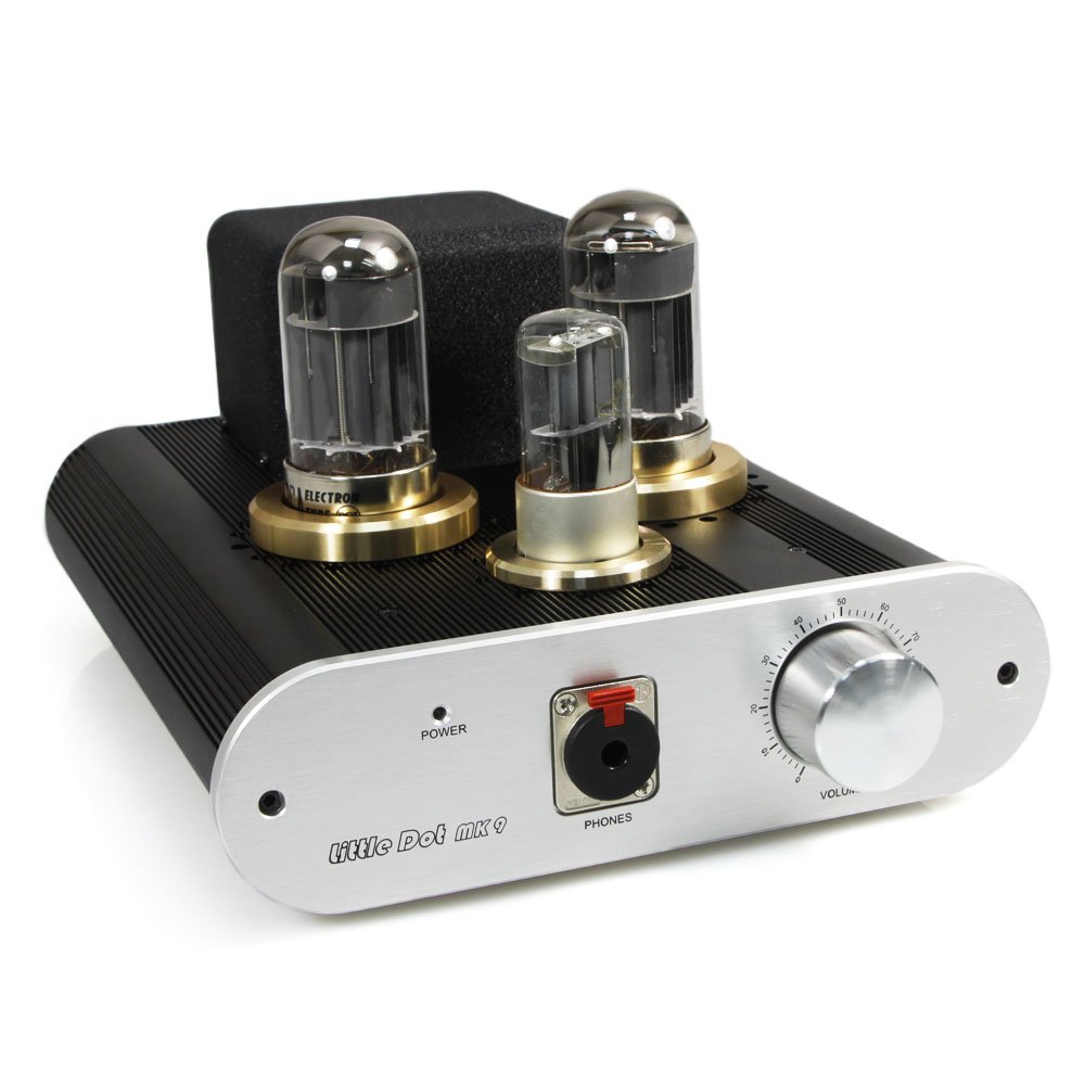
The second thought is that the new Little Dot MK9 is a three tube amp, but with very different tube complement.
 
61lxoMOGOAL._SL1000_.jpg

How would a 12AT7 modded LDIII compare to a LD MK9?
 
A quick sweep of Ebay shows many bargains to be had in all these tube types, 12AT7, and for the MK9 6N9P and 6080 tubes; some even in the 99c stores.
 
My question now, however, is that I am very happy with the 6N6P-IR/6DT6-6AV6 combination. Would further modding of the MKIII yield greater sonic results? Would the MK9 sound appreciably better?
 
Sep 22, 2013 at 3:20 PM Post #3,028 of 13,434
  Hi AFB,
 
Why don't you ask the designer of the MKIII/MKIV directly about the resistor values? His name is Sword Yang and the email address is :    little.tube@gmail.com

 
I did :wink:
 
Just waiting for the answer now!
 
About using one tube instead of two on the MK III / IV : imo, it would be a great solution, theoretically. One problem is purely on an esthetic level, and the other one on a practical level.
 
I'm pretty sure we could work out somekind of an adapter to use one 12Ax7 (x = T / U / X...) on a Mk III, and not have it look too ugly. But it would still be cumbersome to have a single tube kind of floating there with a lot of hidden cabling to reroute the pins to the right sockets. On the MK IV, this kind of an adapter would just look downright ugly...
 
On the other hand -and for a small amount of extra $- a pair of 12Ax7 could be fairly easily adapted on each channel and socket and both look OK or decent, and also be a bit more practical to handle. The added bonus is that a center-tapped 12V double triode could be used with only one heater and triode section powered, and be both economical power-wise and also leave a brand new triode section for the future. Not that bad of an idea, if we look at it long term.
 
However, the other double triode I've been investigating, the 6922/6DJ8/ECC88 supposedly "better" and/or "more linear", does not behave like that at all. It is a 6V, not center-tappable tube, meaning that both triode sections are always powered regardless of use.
 
I've actually just bought 6 very nice EI "Yugoslavia" ECC88 tubes, made on Philips gear with the sought after Philips/Amperex "A-frame" getters, that I will be testing when I get them. I intend to eventually test those on separate 9-pin sockets -attached to 7-pin adapters for convenience- but I might also try them as actual double triodes for both channels.
 
So the problem I am going to bump into here, is that unused-yet-heated triode section for each channel... Note that legend would have it that the two triodes in each tube could somehow be paralleled, but I suspect that that would be for very different amp schematics. Also note that this is why I want to have those resistor values; these tubes could possibly put out 5 times their rated plate current -and dissipation- if biased like 6AK5 might be in our amps, so for once, I'm trying to check things out before hand. they seem to like 90V of plate voltage; our usual tubes are closer to 200...
 
Anyway, just food for thoughts, as usual. I told you I had ideas on the back burner :wink: .
 
Sep 22, 2013 at 3:35 PM Post #3,029 of 13,434
Keep them thoughts coming - always fascinating to read about it! Once things shake out I'll be looking for tubes to try, but the stuff you are doing is beyond my abilities....
 
Good luck, and don't make any fireworks!
 
Sep 22, 2013 at 4:29 PM Post #3,030 of 13,434
I have the pictures taken and a rough schematic made of the amp. Give me a few hours to assemble the info into a presentable format. I have some building maintenance to do first. :D
 

Users who are viewing this thread

Back
Top