Phase noise is indeed frequency modulation. Essentially any real oscillator or other device will not have absolute perfect/infinitely accurate timing, and any modulation of the timing reference will create sidebands. If you want to create a 'pure' tone, you have to have a perfect timing reference. Otherwise if it's either outright running at 0.9999x the intended rate it'll output a 999.9hz tone instead of 1khz. And if it is not constantly at exactly 1.00000x the intended rate, instead shifting phase slightly over time and causing the output to MOSTLY produce 1khz but a little bit of 1.0001khz and 0.9999khz etc, we will see a spread toward the bottom of the FFT as there is some content that is not exactly 1khz.
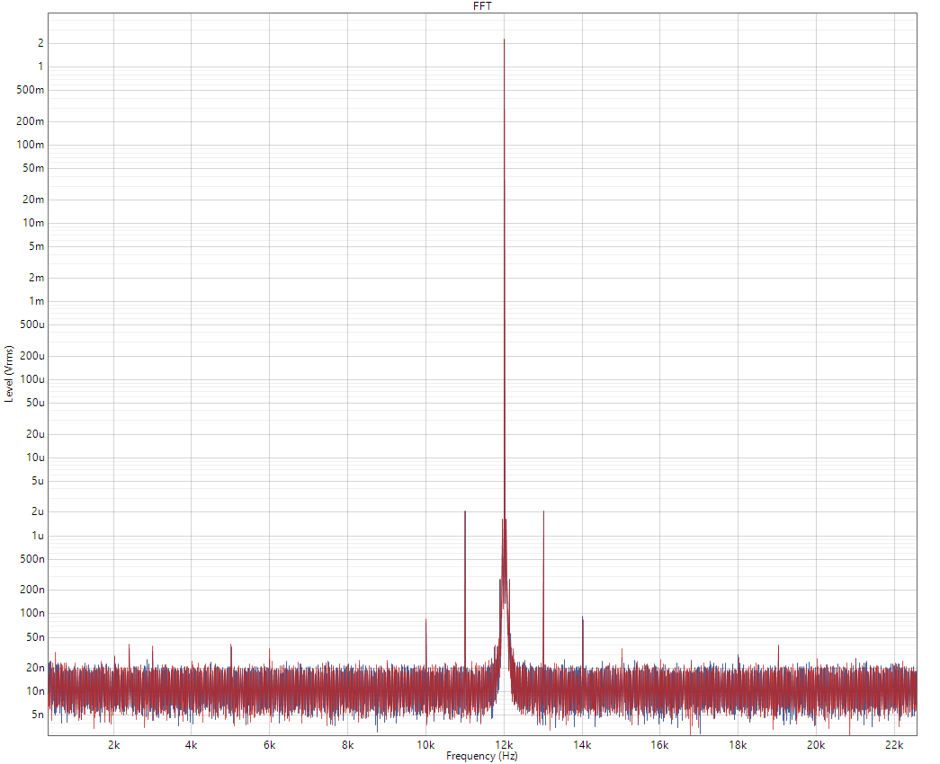
If these jitter components are at a higher and fixed frequency, such as if there's potentially interference from some switching component in the device, then this will show up as a single spike. For example with this example device, if I add a meaningful amount of 1khz jitter, and the fundamental tone is at 12khz, then we see spikes at 11khz and 13khz (plus some at multiples of those sometimes):

If I change the jitter frequency to 3khz, then this jitter moves to 9khz and 15khz, which is 3khz either side of the fundamental.
We still have the multiples as well, but also note that the level shown for the 9/15khz spikes is now lower even though the jitter level I'm adding is the same, this is just because PLLs are typically more effective at higher frequencies, they are low-pass filtered in practice, and so it can attenuate 3khz jitter a bit more than 1khz jitter.

If we keep the 3khz jitter, but change the frequency the DAC is outputting to 15khz instead, now we see the jitter components at 12khz/18khz (plus multiples).

It's still 3khz either side of the fundamental, because the sidebands we see are a result of modulation between the jitter frequency and the fundamental the device is outputting. So if we have 100hz jitter it'd be 100hz either side, 10khz jitter it'd be 10khz either side, doesn't matter what frequency the DAC is outputting.
'Phase Noise' and Jitter are not from an absolute perspective different from one another, they are both frequency modulation of the output due to the timing reference not being 100% perfect. Essentially if the device is TRYING to output a pure 1khz sine, but the timing reference is not always constant, sometimes being a little closer to 1.0001x what it should be or 0.9999x what it should be, then we will see very low frequency modulation of the output. 'Phase noise' is more just the name most often used to describe these low frequency 'frequency uncertainty' components so to speak. It's 'noise' about the intended frequency rather than a single deterministic jitter component. Though you can absolutely have wider bandwidth random jitter too and this will show up as a modulation of the noise floor itself in a wider area than the 'skirt'.
As to measuring phase noise, it's pretty simple and we just do what we described above, run an FFT and look at how the low-frequency jitter/phase noise components (meaning stuff close to the fundamental) shows up.
Here is a device running off a timing reference with high phase noise:

And now here's that same device running off a much lower phase noise timing reference:

The low frequency phase noise is drastically lower and therefore the bins close in to either side of the fundamental are much lower, since the device just isn't outputting stuff at those frequencies any more, it's much closer to a pure and exact 15khz sine with less timing error. This produces what looks visually like a thinner stem with a much lower/thinner 'skirt'.


 . I'm gonna repeat they are certain things you can't measure..synergy and jenesequa. This uddc brings that to my system
")


