"I'm not dead yet!" ...A Balanced LTP/Jisbos Tube Hybrid
Aug 9, 2014 at 11:47 AM Thread Starter Post #1 of 26

Zaubertuba

100+ Head-Fier
Joined
Feb 3, 2009
Posts
449
Likes
23
This has been rattling around in my brain for months, but I've finally made enough consistent progress to see the light at the end of the tunnel.  I've had the Jisbos/Alpha 20 boards from AMB for awhile, but have only recently gotten comfortable enough with tube design to get a reasonable prototype running (well, at least one channel).
 
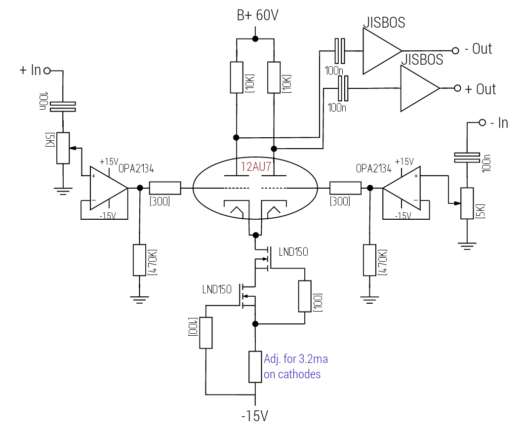
Basically, this will be a long-tailed-pair 12ax7 input/gain stage followed by an AMB JISBOS buffer.  I'll use a CCS to improve balance.  As I'm trying to do this with as many "on-hand" parts as possible, some of the choices may seem, well, a little eccentric, but individualism is what this is all about, right? 
wink.gif

 
The LTP circuit I adapted from the basic design outlined by Merlin Blencowe in his awesome "Designing Tube Preamps for Guitar and Bass."  I know it's really not a book geared for HiFi, but it's a great intermediate text that gives enough info. to truly know what the heck you're doing when you're working with tubes, whether you're trying to run them "clean" or overdrive them.
 
I don't have access to fancy test equipment--just my old multimeter, so most of this is old-school hammer-and-tongs math followed by listening tests.
 
 
My "on-a-napkin" schematic:


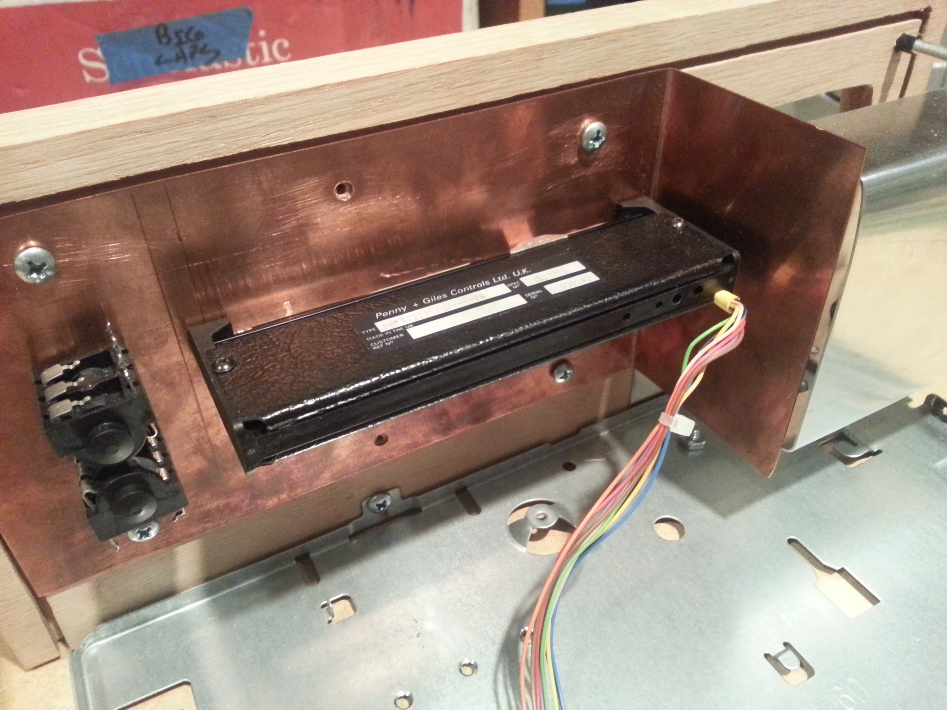
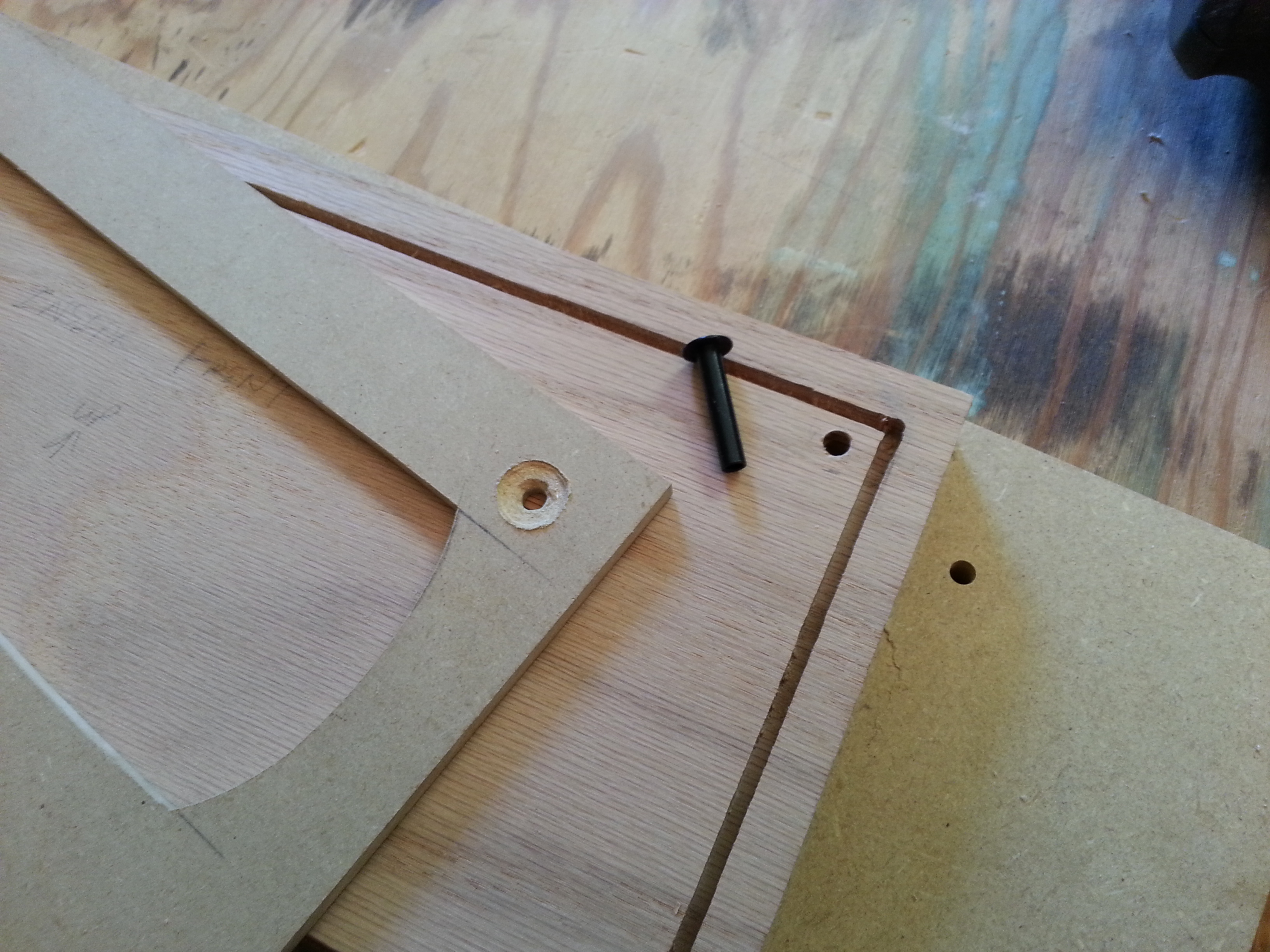
I expect to do more tweaking even on this final build, so I'm using old-fashioned guitar amp terminal strips for a lot of the circuit--here's the planned layout:

 
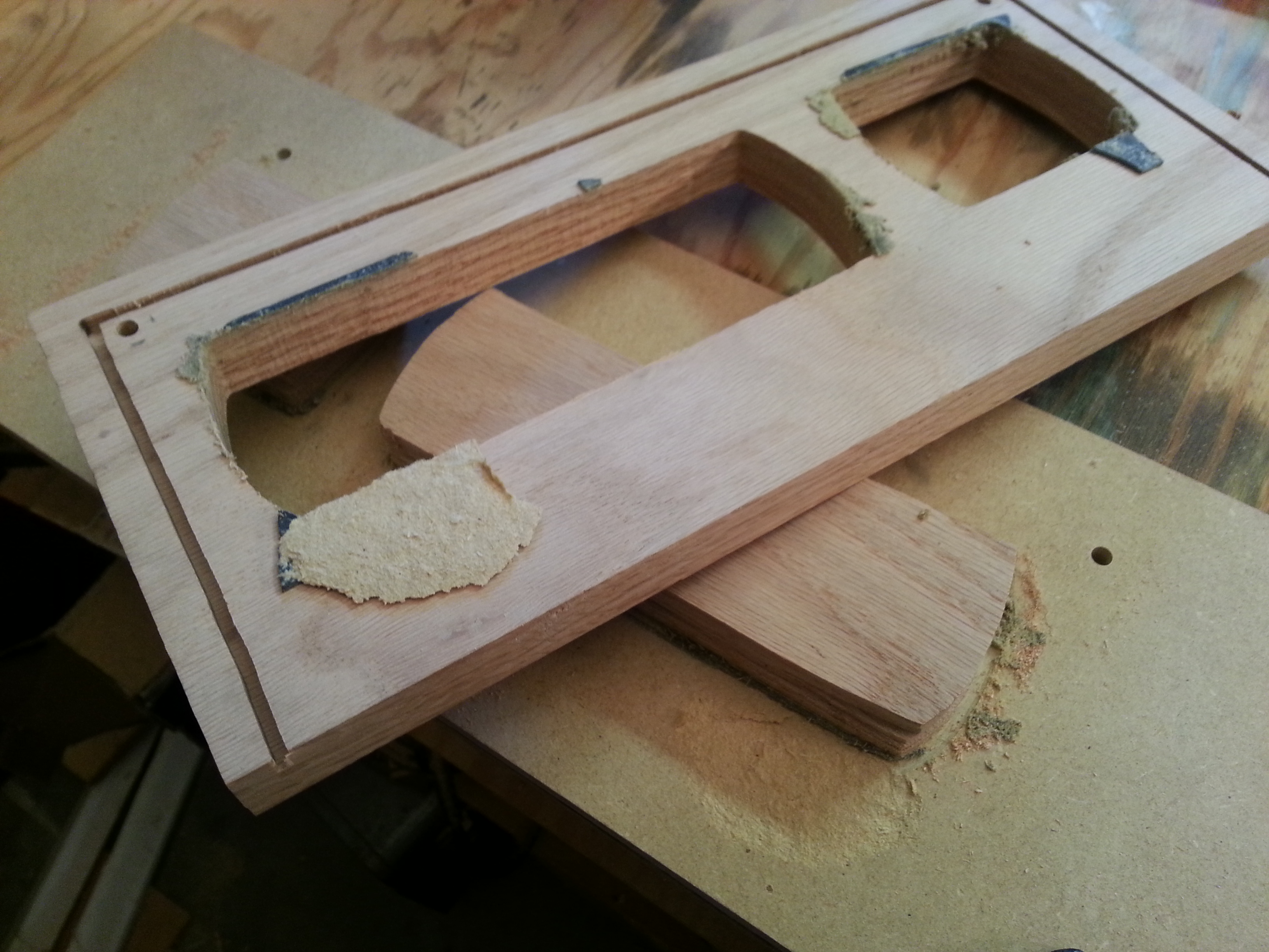
Some of the component parts (hand-fashioned copper chassis top in the background
cool.gif
):

The Dale resistors I found at this awesome electronics recycling shop we have in downtown Boise--they'll be used for the anode resistors and grid-stoppers.
 
Comments and suggestions are of course always welcome.  Let the fun begin! 
smily_headphones1.gif
 
 
Aug 15, 2014 at 3:10 AM Post #2 of 26
There is much about the schematic that is likely sub-optimal: the CCS probably won't have sufficient voltage across it which will lead to clipping, the plate loads are too low which increases distortion, the tube's mu is too high, the grid stoppers are unnecessarily large, the pots after the tube are problematic for distortion and clipping reasons, and they are of too low an impedance anyway -- it should be 10x the output impedance, not 1/10th. Doesn't the buffer need a negative supply? Use that for the tail of the CCS. Doesn't solve every problem, but it is a start.
 
Aug 15, 2014 at 5:33 PM Post #3 of 26
Thanks so much for giving my napkin a look, dsavitsk!
There is much about the schematic that is likely sub-optimal: the CCS probably won't have sufficient voltage across it which will lead to clipping, the plate loads are too low which increases distortion, the tube's mu is too high, the grid stoppers are unnecessarily large, the pots after the tube are problematic for distortion and clipping reasons, and they are of too low an impedance anyway -- it should be 10x the output impedance, not 1/10th. Doesn't the buffer need a negative supply? Use that for the tail of the CCS. Doesn't solve every problem, but it is a start.

 
-The CCS should be an easy fix--the only reason I was pulling the base voltage from the HT was my low-voltage supply floated in my mock-up. The low-voltage supply does have a negative rail.
 
-I have some lower-mu tubes around but the 12ax7's were the only ones I at least had a similar pair of.  I do have some 12at7's or 12au7's I can work up, and order better-matched tubes later, I suppose.  I gravitated away from the 12au7's originally because I read something on another forum that suggested 12au7's aren't particularly linear--might've been a silly comment.  I'll redo my load line for a higher plate load while I'm at it.  Back to the recycling shop!
 
-I'll go back and check my math on the Grid-stoppers.  Seems I remember I actually was conceding by making them lower than what I initially calculated...hmmmm...
 
-I know my faders are small, but does it really matter when my input impedance for the JISBOS is nominally 1 Megaohm?  I know it sounds silly but the P&G faders are my cheap workaround for not having to get an expensive quad-pot.
 
Thanks again--and back to the drawing board.  :wink:
 
Aug 15, 2014 at 11:20 PM Post #4 of 26
Criticisms of the 12AU7 are over stated. No, it is not the best tube ever made, but the nonlinearities are subtle and will pail in comparison to other issues.

-I'll go back and check my math on the Grid-stoppers.  Seems I remember I actually was conceding by making them lower than what I initially calculated...hmmmm...


There's no real math to do for grid stoppers. Use something in the 100-1000 Ohm range. If you start working with really high gm tubes (7788, 6H30, etc.) then it may be more of an issue.

-I know my faders are small, but does it really matter when my input impedance for the JISBOS is nominally 1 Megaohm? I know it sounds silly but the P&G faders are my cheap workaround for not having to get an expensive quad-pot.


The pots are in parallel with the plate load resulting in a very low load for the tube. The upside is that this will reduce your gain considerably. The downside is that the distortion will be pretty high and your will likely lose frequency response.
 
Aug 16, 2014 at 8:19 PM Post #5 of 26
I *really* appreciate the feedback. Learning a lot here. 
cool.gif

 
Criticisms of the 12AU7 are over stated. No, it is not the best tube ever made, but the nonlinearities are subtle and will pail in comparison to other issues.
 
Thanks, I'll start there, then.
 
There's no real math to do for grid stoppers. Use something in the 100-1000 Ohm range. If you start working with really high gm tubes (7788, 6H30, etc.) then it may be more of an issue.
 
Allright that's an easy fix.
 
The pots are in parallel with the plate load resulting in a very low load for the tube. The upside is that this will reduce your gain considerably. The downside is that the distortion will be pretty high and your will likely lose frequency response.
 
Ah, I gotcha. *lightbulb goes on* ...actually kinda embarassed I didn't see that.
redface.gif

 
So I'm running into a quagmire:  I did a couple of load lines for the 12au7, thinking raising the plate resistance a lot higher could mitigate the low pot value issue somewhat.  The problem is this:


Using higher value plate resistors with the 12au7, the load lines are ending up pressed way down towards the abscissa, where the grid curves start bunching up.  Doesn't this increase 2nd harmonic distortion?
confused.gif

 
Looking at the plate curves it looks like I'll run into the same problem with the 12at7.
 
I mean, I suppose I could bias it on the warm side, at -6v or even -4v, but then I'm reducing headroom, which seems silly when I've got a reasonable B+ around 315v.


So if I stick with the 5k faders, it looks like I'm not going to get around using a buffer before them, am I right?
tongue_smile.gif


Aug 16, 2014 at 9:47 PM Post #6 of 26
...and I'm sure the electronics bench tube-lesson will continue. Meanwhile, in the garage, I've made some advancements in the case-work...
 
 
Lubrication and a bi-metal hole saw works surprisingly well when you can't afford a $45 step-bit:


Drilled and marked-up sheet ready for bending in my home-made metal brake:


I had to cut a pocket in the brake to fit the compound bend:


Completed tube bracket.  I'll polish the visible parts to a mirror finish before final assembly:


Front panel. The fader slots were painstakingly hand-machined over an evening with a Dremel and several different bits.  I do have a smaller step-bit for the 1/4" jack holes.
wink.gif


Aug 16, 2014 at 11:02 PM Post #7 of 26
Those are your DC load lines which set the operating point. But the AC loadlines will be, e.g., 68K || 5K which is much steeper. Usually one does not make a distinction as the Zin of the next stage is super high.

For a pot, look into using a differential shunting pot. By putting the pot after the gain stage, you are generating maximum distortion. If the pot is first, then you only generate what you need.
 
Aug 17, 2014 at 9:54 PM Post #8 of 26
Boy that's a lot more elegant solution. So from what I read, it sounds like putting the series resistors at 90% of the value of the shunt pots preserves the pot curve the most and provides the least attenuation at full volume.  Closest value is 4.7k, so, a balanced shunt using my faders before the ltp might look something like...
 

Am I on the right track?  Seems like getting the pot out from between the ltp and the JISBOS as you suggest would cover a multude of sins from my original schematic. At least my source is solid-state and should be up to it. 
tongue.gif
 
 
Aug 24, 2014 at 7:29 PM Post #9 of 26
I drew up the schematic in a format that should be a little easier to read. 
wink.gif


Another question...Q1 is actually a darlington pair.  I thought I had a grasp of calculating the current for the CCS but well, now I'm not so sure...
redface.gif

 
...can anyone recommend a good reference on the topic?


EDIT: Forgot the tube label!
rolleyes.gif
 
 
Aug 25, 2014 at 12:32 AM Post #11 of 26
...Doesn't the buffer need a negative supply? Use that for the tail of the CCS. Doesn't solve every problem, but it is a start...

 
  the -15 should be +15

 
LOL I was just going through all sorts of the mental gyrations you'd expect when you have two experts giving you conflicting information, when I realized I have to use a different CCS to do what dsavitsk is suggesting, anyway.
redface.gif
 
 
By the way thanks for posting Kevin, and I love the title on your calling card--my Dad used to use that phrase from time to time, and I've found myself using it as well.
smile.gif

 
Aug 25, 2014 at 4:04 AM Post #12 of 26
For the ccs, there's a simple explanation in here : https://www.passdiy.com/pdf/diyopamp.pdf . Go to fig 15 and the accompanying text. Don't forget that, with a darlington, you have two vbe drops instead of one.
 
Imo, your schematic is not a very good idea. You'll have too much gain, even with 12au7, and that is made worse by going balanced. And I'm not quite sure which benefits you hope to get by going balanced for headphones... been there, done that, waste of ressources. With what you have on hand, a 12au7 SRPP followed by a single solid state buffer seems a decent option.
 
Aug 25, 2014 at 9:59 AM Post #13 of 26
  For the ccs, there's a simple explanation in here : https://www.passdiy.com/pdf/diyopamp.pdf . Go to fig 15 and the accompanying text. Don't forget that, with a darlington, you have two vbe drops instead of one.
 
Imo, your schematic is not a very good idea. You'll have too much gain, even with 12au7, and that is made worse by going balanced. And I'm not quite sure which benefits you hope to get by going balanced for headphones... been there, done that, waste of ressources. With what you have on hand, a 12au7 SRPP followed by a single solid state buffer seems a decent option.

 
Thanks-I'm looking forward to looking through that pass article.
 
I really appreciate you wanting to keep me from going down the wrong dark path (I do that with my son sometimes  
wink.gif
).  Here's my dilemma with changing the topology this late in the game:
 
-I've already invested in a balanced setup and the bulk of the components for this balanced build (including some of the casework which would involve scrapping some expensive copper I won't be able to use in an SE build).
 
-I'm using a simple pi-filter for the HT supply and direct AC from the transformer 6.3v tap for the heaters.  On my test bench, with no shielding and a hornet's nest of wires, my mock-up was startlingly quiet.  If I went single-ended I'd likely have to build new HT and heater power supplies. This would be more cost and work for me than it may at first seem. 
 
-We're in a fairly noisy EMI area--we sometimes have that nasty cell-tower interference break into my receiver and speakers--I'm surprised it hasn't blown my speakers yet.  I do not want that crap getting randomly injected directly to my ears. 
 
Once I've figured out how to do a proper CCS, I'd rather try even lower mu triodes than scrap what I've already done entirely.  Surely I can come up with something that sounds better than my hacked-together a47 build (which isn't really even a proper "balanced" build, per per-se)?
 
Aug 26, 2014 at 1:07 AM Post #15 of 26
You're right--I was trying to fully utilize my stereo pots but the legitimate shunt would probably work better anyway.  Fixed.
 
I also redid the CCS.


I was just thinking, perhaps I could add some local NFB to tame the gain a bit?
 

Users who are viewing this thread

Back
Top