soMn
100+ Head-Fier
- Joined
- Dec 30, 2005
- Posts
- 156
- Likes
- 10
Just my meager contribution here. I've had all this info for about a year and a half, so I know it's not anything new, but I couldn't find any threads here about it, and I was anxious to put it to use using what I'd learned from the interconnect thread.
To be completely clear, this post is merely the synthesis of brschmid's interconnect thread, and this one by Sirronikae over at iaudiophile.net. I had made a few of these cables when I first got my X5L about a year and a half ago (line-out, line-in, and two portable USB cables), but for the audio cables I simply used a cheap radioshack RCA cable, cut in half. But after getting my first set of Grados and a PA2V2, I felt I needed a line-out to mini; plus I just wanted to play with techflex and heatshrink, and I had an extra Gomadic connector from before (also I needed something small and inexpensive to help stave off the upgraditis). I know some people have issues with the X5 line-out, but to my (admittedly untrained) ears, using the line-out with amp seems, at the very least, to clear up the problem with somewhat muddy or less detailed mids. Nor have I noticed a decrease in bass, and I listen to quite a bit of <gasp> hip-hop, though lately it's been mostly jazz and folk. Also, the volume of the line-out doesn't exactly change with the volume control as I had seen some people indicate. Firstly, it doesn't really change at all when you're running Rockbox; if it's down completely, then it's muted, but if you turn it up all the way the volume stays constant. Then in the iAudio software it's muted at 0, then constant through 34, where it jumps up through 40. I never noticed it because I always boot to Rockbox anyway.
One last thing before getting to the pictures; in Sirronikae's thread there's a link to Gomadic and he identifies the part needed as #ICP-21-1700, which was correct when I bought my first batch. Now, however, I think the part # is simply ICP-21. I'm not completely positive (99% sure), but I'll know later this week when the two that I just ordered come in. To the connector I'm attaching Canare star quad, and their F-12 mini.
I didn't take many pictures of the steps of the assembly that are already covered in greater detail by either author, just a few to help with the assembly of the connector, and to show the end product, of course.
Here are the parts of the Gomadic connector when you receive it unassembled:

Unfortunately, there are no instructions for assembly, but it's rather easy and intuitive; the only thing you need to be careful about is to get the locking prongs facing the correct direction (downward):

If you look at the pic 4 down from here (not counting the pin-out diagram), the one of the connector mostly assembled, you can see on the plate that isn't snapped on yet that there are two little triangles on either side whereas the one in this pic is smooth. The above pic is of the bottom of the connector whereas the final piece in the almost complete connector is the top.
Comparing this diagram (from the iaudiophile.net forums)
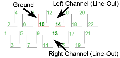
to this pic

shows the proper orientation of piece with the pins (sorry that it's blurry; there was just enough light to keep the camera from flashing in macro mode). I drew the red lines to help delineate pins 1 and 2.
Obviously, it's much easier to solder without all of the extra pins in there, though removing them isn't necessary to making it work. Just remove them using needle-nosed pliers:
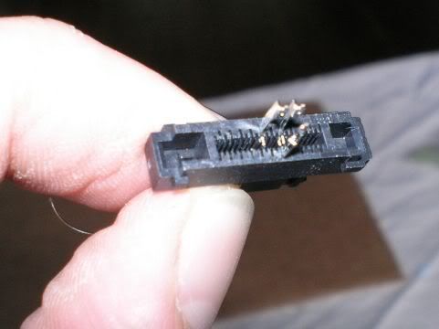
Here it is after soldering. I used small diameter heatshrink to ensure that the soldered pins and wire stay separated.
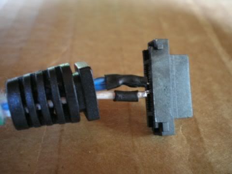
I debated about using the sleeve that comes with the connector, and in the end I kinda wish I hadn't because I probably could have made the techflex and heatshrink seamless without it. Oh well, live and learn. As I mentioned before, I have two more on the way.
Here it is almost completely assembled:
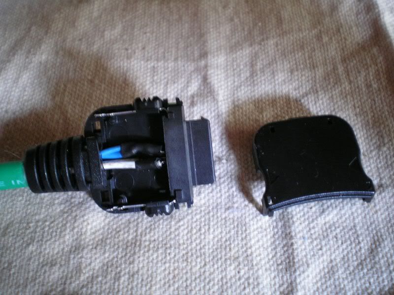
Although it should be obvious just by looking at the connector on the iAudio, you can tell how to orient the piece with the pins in the enclosure because the flat side is up and the grooved side is down.
Finished cable:
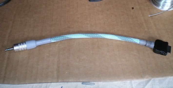
I got sloppy with the heatshink and techflex on the connector side -- something I'll remedy next time around.
and here it is in action:
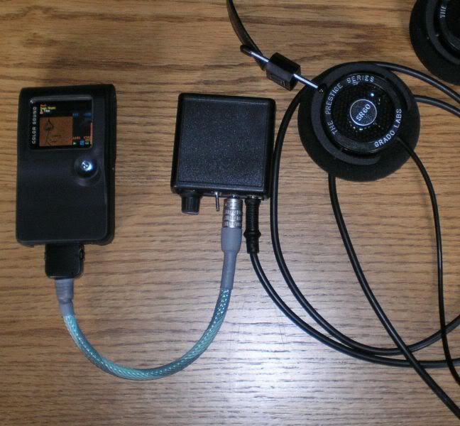
I hope this helps anyone with an X5. I love mine, despite having such flaws as that stupid subpack and the joystick. Next project: I want to replace my crappy line-in, as I often record a friend who spins at my sister's coffee shop, and it's so convenient to be able to just plug straight into his mixer.
Also, I have a detailed PDF that includes all of the info in Sirronikae's thread, along with complete pin-outs of the X5 and the subpack and instructions on making a retractable USB cable (very convenient; one of the first things I made). I can't remember who originally made it, but it's basically just compiled from the iaudiophile forums. PM me if you want a copy and I'll email it (450K).
To be completely clear, this post is merely the synthesis of brschmid's interconnect thread, and this one by Sirronikae over at iaudiophile.net. I had made a few of these cables when I first got my X5L about a year and a half ago (line-out, line-in, and two portable USB cables), but for the audio cables I simply used a cheap radioshack RCA cable, cut in half. But after getting my first set of Grados and a PA2V2, I felt I needed a line-out to mini; plus I just wanted to play with techflex and heatshrink, and I had an extra Gomadic connector from before (also I needed something small and inexpensive to help stave off the upgraditis). I know some people have issues with the X5 line-out, but to my (admittedly untrained) ears, using the line-out with amp seems, at the very least, to clear up the problem with somewhat muddy or less detailed mids. Nor have I noticed a decrease in bass, and I listen to quite a bit of <gasp> hip-hop, though lately it's been mostly jazz and folk. Also, the volume of the line-out doesn't exactly change with the volume control as I had seen some people indicate. Firstly, it doesn't really change at all when you're running Rockbox; if it's down completely, then it's muted, but if you turn it up all the way the volume stays constant. Then in the iAudio software it's muted at 0, then constant through 34, where it jumps up through 40. I never noticed it because I always boot to Rockbox anyway.
One last thing before getting to the pictures; in Sirronikae's thread there's a link to Gomadic and he identifies the part needed as #ICP-21-1700, which was correct when I bought my first batch. Now, however, I think the part # is simply ICP-21. I'm not completely positive (99% sure), but I'll know later this week when the two that I just ordered come in. To the connector I'm attaching Canare star quad, and their F-12 mini.
I didn't take many pictures of the steps of the assembly that are already covered in greater detail by either author, just a few to help with the assembly of the connector, and to show the end product, of course.
Here are the parts of the Gomadic connector when you receive it unassembled:

Unfortunately, there are no instructions for assembly, but it's rather easy and intuitive; the only thing you need to be careful about is to get the locking prongs facing the correct direction (downward):

If you look at the pic 4 down from here (not counting the pin-out diagram), the one of the connector mostly assembled, you can see on the plate that isn't snapped on yet that there are two little triangles on either side whereas the one in this pic is smooth. The above pic is of the bottom of the connector whereas the final piece in the almost complete connector is the top.
Comparing this diagram (from the iaudiophile.net forums)

to this pic

shows the proper orientation of piece with the pins (sorry that it's blurry; there was just enough light to keep the camera from flashing in macro mode). I drew the red lines to help delineate pins 1 and 2.
Obviously, it's much easier to solder without all of the extra pins in there, though removing them isn't necessary to making it work. Just remove them using needle-nosed pliers:

Here it is after soldering. I used small diameter heatshrink to ensure that the soldered pins and wire stay separated.

I debated about using the sleeve that comes with the connector, and in the end I kinda wish I hadn't because I probably could have made the techflex and heatshrink seamless without it. Oh well, live and learn. As I mentioned before, I have two more on the way.
Here it is almost completely assembled:

Although it should be obvious just by looking at the connector on the iAudio, you can tell how to orient the piece with the pins in the enclosure because the flat side is up and the grooved side is down.
Finished cable:

I got sloppy with the heatshink and techflex on the connector side -- something I'll remedy next time around.
and here it is in action:

I hope this helps anyone with an X5. I love mine, despite having such flaws as that stupid subpack and the joystick. Next project: I want to replace my crappy line-in, as I often record a friend who spins at my sister's coffee shop, and it's so convenient to be able to just plug straight into his mixer.
Also, I have a detailed PDF that includes all of the info in Sirronikae's thread, along with complete pin-outs of the X5 and the subpack and instructions on making a retractable USB cable (very convenient; one of the first things I made). I can't remember who originally made it, but it's basically just compiled from the iaudiophile forums. PM me if you want a copy and I'll email it (450K).


