How would you explain this distortion (fft pics inside)
May 25, 2009 at 8:36 PM Post #16 of 38
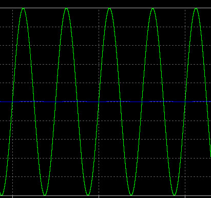
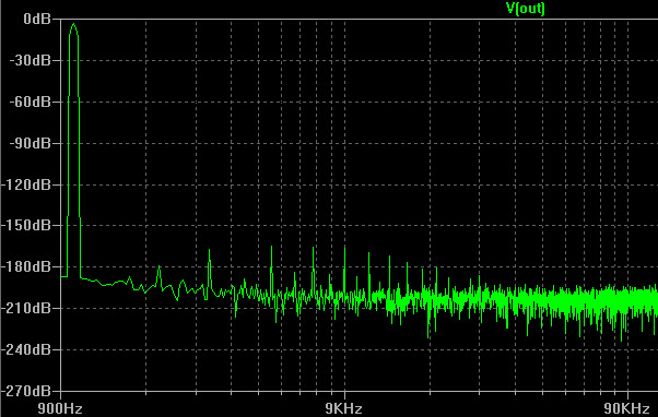
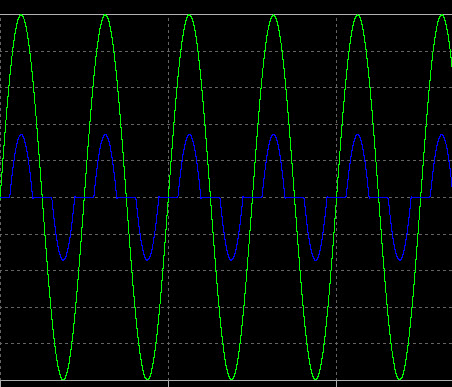
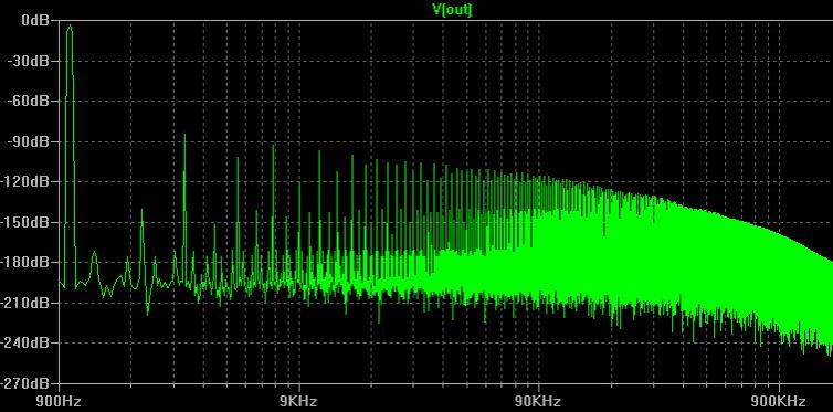
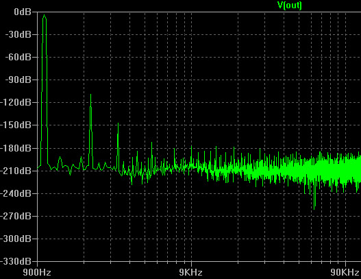
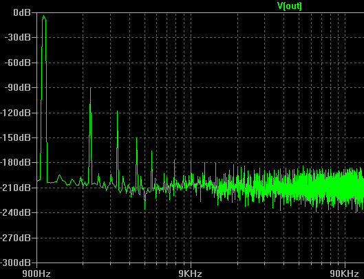
And this is how it looks with a passive ground a la CMOY, two 1000 uF electrolytics and two 1k resistors. Still 1V output and 50R load.

I think this myth is ... plausible!

attachment.php

attachment.php


May 25, 2009 at 8:48 PM Post #17 of 38
Quote:

Originally Posted by goodsound /img/forum/go_quote.gif
diditmyself, I am sorry I am not able to see your point. I thought you said something about showing simulations as to how a 3-channel confuguration has an impact of this nature.


It was just to show you what to expect from a class AB amplifier under heavy load. I think AD8620 is at the edge of it's limits when you run RMAA with a low Z phone.
 
May 25, 2009 at 9:03 PM Post #18 of 38
Quote:

Originally Posted by goodsound /img/forum/go_quote.gif
jcx, looks like our posts crossed.

There is no effect on the amount of distortion in both thd or imd whether only one channel is driven or both.

I did your 'cross channel' imd test. 60hz in the left channel and 7Khz in the right channel, both at 0db. Here are the results -

No Load -
The 7Khz signal was found to be at -80db in the other(left) channel as well.
The 60hz signal was found to be at -60db in the other(right) channel as well.
There were no IMD distortion components to be found.

One channel loaded -
same as above.

Both channels loaded -
same as above + the same IMD distortion as reported in my original post!

I did the same test on the Headsix and once again point to be noted is that this imd distortion is not existent at all in the Headsix. No such thing whatsoever.


So what does this prove ? That the ground channel in the V6 is not isolated enough ?
...


I think your results are consistant with the active ground AD8610 in the GV6 not having enough output current capability to linearly sink both channels' load current at once - where this has to be interperted as "not enough to do the job without any sign of (nonlinear) strain under a microscope at really high output"

this is still not likely an audible level of distortion - at the high end of its design SPL any dynamic driver will have much larger IMD from motor and suspension nonlinearities

the biggest audible concern is distortion that doesn't continue decreasing relative to signal as the signal level decreases; i.e. crossover distortion

there is still some room for other players - the GV6 appears to have a dual channel op amp where the Headsix has 2 monos? - I can't make out their part #'s
 
May 25, 2009 at 9:30 PM Post #19 of 38
Quote:

Originally Posted by jcx /img/forum/go_quote.gif
there is still some room for other players - the GV6 appears to have a dual channel op amp where the Headsix has 2 monos? - I can't make out their part #'s


thats correct. Two AD8610s in the Headsix v/s Two AD8620s + One AD8610 in the GV6.

and that is why I am not able to quite readily accept the idea that it's because of insufficient output capability of the opamp. They are virtually identical in that respect.

Do also note that the level at which these tests were done are far lower than that limit. IIRC the voltage I measured across the 75ohm headphone was somewhere in the 0.5 - 0.6V range which equates to merely 10ma per channel, and also translates to SPLs already more than real world 'normal' listening levels.
 
May 25, 2009 at 10:24 PM Post #20 of 38
the "3 channel" topology puts both output channel currents through the single active ground op amp - meaning 2x the current flow in the active gnd op amp when both R/L channels have the same signal - and "3 channel" separates the input signal ground from the output gnd

this means any movement of the buffered output gnd in response to sinking the 2 channels of load current appears in series with the signals


another test that could nail it is to do the IMD both channels loaded but with the polarity of the IMD test signal reversed in one channel - for equal R/L loads there would be no gnd channel current and the IMD products should disappear if the gnd channel is the culprit - if it doesn't then maybe the duals have some other IMD generation mechanism


I prefer keeping output and signal gnds together, these portables are a good application since the in and out conn are close together giving a near "star gnd"

if the GV6 circuit is a classic "3 channel amp" then I'd expect much of the IMD could be eliminated by changing it to a buffered splitter driving a common gnd - esp with the large plane and close location of the i/o

from what I can see in the photos it looks like cutting the TLE out and AD8610 +in free of the gnd plane and wiring them together, then shorting the output conn gnd to the plane could do the trick

I'm not offering a warranty on that suggestion however
 
May 26, 2009 at 10:53 AM Post #21 of 38
Quote:

Originally Posted by Horse /img/forum/go_quote.gif
The flaw is in the active ground topology. Also sonically, as I have personally experienced -- the 3 channels introduce a degree of unnaturalness in treble and in 'space' (which I guess is why some love it), plus a certain thinness or lack of meat to vocals etc. (which is the main reason why I hate it).
popcorn.gif


Let's not confuse personal bias or subjective impressions as technical fact, shall we?
rolleyes.gif


I have several 3-channel active ground amps in my lineup, none of which exhibits the above distortions. I will say that in order for an active ground topology to work well, all three channels must be very robust. AD8610/20 is simply not strong enough to drive the headphone load directly in this role, and it's not fair to infer that there is something intrinsically flawed about 3-channel active ground topology based on that example.
 
May 26, 2009 at 11:13 AM Post #22 of 38
Quote:

Originally Posted by Horse /img/forum/go_quote.gif
That was my guess too (based on my experiences even with high current ground channel opamps). In other words, it is NOT the best topology for portable or accessible amps...


You're forgetting the Mini³ v2 high performance edition. It doesn't have those distortions either, and it's based on high current opamps (AD8397 + OPA690).

Quote:

No wonder no commercial brand uses it in such cases.


There are quite a number of commercial amps using 3-channel active ground topology; portable, transportable or desktop.
 
May 26, 2009 at 11:43 AM Post #23 of 38
Quote:

Originally Posted by Horse /img/forum/go_quote.gif
LOL true, I forgot a couple of sellers of cheapish portable amps designed by themselves.
biggrin.gif


I appreciate the smirk, but that's a cheap shot (pun intended).

Some of the 3-channel commercial products out there are hardly "cheapish", and the topology certainly isn't cheaper than a conventional 2-channel one.

I won't comment on your subjectives, that would be a useless discussion and go absolutely nowhere.
 
May 26, 2009 at 2:29 PM Post #24 of 38
Horse, with a passive ground you get substantially more crosstalk in the bass and mid regions. So you'll get the fuzzy sound of electrolytic capacitors and a more monaural presentation. This coloration can often synergize with the coloration of many modern high quality opamps like LME49720.

Ground channel amps, most often running at unity gain are problematic to get stable, so you can't really evaluate the sound of such an amp without knowing if there's ground channel oscillation, ringing or any other misbehaviour. Using AD8610 as a ground channel amp is IMO bad engineering.

Soundwize an amp with a well implemented ground channel should sound about the same as one with low impedance shunt regulators, shouldn't it. You'll rarely find such amps in the bargain basement.
 
May 26, 2009 at 3:43 PM Post #25 of 38
passive gnd (common gnd plane) is very linear if you route the circuit so that any nonlinear Class B return currents substantially don't flow between signal, output and feedback gnd points - with Class A outputs even that distortion mechanism goes away


linear, frequency independent cross talk from common ground impedance is not likely to audibly objectionable - after all "musically superior" analog phonograph playback seldom reaches 40 dB channel separation (the best phono cartridges spec it at a vague > 30-35 dB channel separation)

I see no reason to believe readily achievable -60dB (typical of closed supra-aural closed back phones) to -80 dB linear crosstalk on the PCB of a passive gnd amp is audible with music, open phones have much more interaural crosstalk:

Loudspeaker and headphone handbook - Google Book Search

beyond active vs passive gnd on the PCB you have significant common ground impedance from a stereo TRS 1/4" phono plug-jack interface - 10-20 mOhm contact/series resistance can be much more than a well executed gnd plane or active ground (1/8" mini jack/plug common R likely is even higher)
 
May 27, 2009 at 5:45 AM Post #26 of 38
Jcx, I can't see how to make a passive ground without the signal being degraded by (electrolytic) capacitors. Can't you please show me how to do it. Capacitors in general and electrolytics in particular has non-linear distortion, and I don't like the sound of them.
 
May 27, 2009 at 10:12 AM Post #27 of 38
Quote:

Originally Posted by Horse /img/forum/go_quote.gif
WOW! You're speaking of power supply electrolytics precisely as if they were in the signal path... That's not exactly so, you know.


Yes they are. They're sinking and sourcing the return currents. With a passive ground, I can't see how to avoid them in the signal path.
Quote:

BTW, if the dual power supplies are well regulated, I can't see how the reservoir electrolytics could become so important.
smily_headphones1.gif
I'd say that the regulators are more important... And that's the same for a single power supply powering a 3 channel amp
normal_smile .gif


You can't call the ground in an amp with regulators passive. There are active parts (IC's, tubes, discretes or a combination) sinking and sourcing the return currents. If eg two OPA690s were used in a Mini3 as regulators and creating a virtual ground, would it sound different from a Mini3 with the same OPA690 used as "ground channel"?
Quote:

BTW, how do people happen to want the most technically possible channel separation in a headphone amp?

Headphones have their speakers coupled directly with each ear, and this already makes for a much much unnaturally exaggerated separation between the sounds coming to the R and L ears...
wink_face.gif


For the same reason we want low distortion, low noise etc. I think we want the lowest possible degradation of the sound.
 
May 27, 2009 at 3:18 PM Post #28 of 38
Quote:

Originally Posted by jcx /img/forum/go_quote.gif
another test that could nail it is to do the IMD both channels loaded but with the polarity of the IMD test signal reversed in one channel


did you mean switch the connections of one channel ? Like flip-flop the gnd and hot in one channel ? If so then switch them on the input or output end of the amp ? Or did you mean just change phase of one signal by 180° ? I use WaveGen to generate the signals and there is one setting that I believe contols the phase of the signal. I tried that and the distortion is still there. Maybe I didn't do it the right way ?
 
May 27, 2009 at 3:47 PM Post #29 of 38
my proposed test would be to invert the phase of one channel's IMD test signal keeping amplitude the same in both channels

with both channels equally loaded and driven with the same test signals except for the inverted phase the sum of the current in both channels loads should very closely cancel leaving very little current in the active gnd

I don't know WaveGen, I have used the free Audacity sound editor to make/view/play/record .wav (Sourceforge)
using some wav viewer you should see the L/R signals "mirrored" about the horizontal axis - in Audacity you could add them together and they should cancel

I really would like to hear that with the properly inverted/balanced R/L IMD test signals that the IMD products go away - figuring out where the distortion is coming from otherwise could be difficult


it is correct that the current in the op amp and load completes the loop through the power supply caps but with the common ground "passive" scheme the possible errors/distortions are effectively "inside" the op amp feedback loop so the op amp's excess loop gain and psrr reduce the effects the same way the negative feedback reduces the distortion of the op amp's own Class aB output stage


2 other possibilities occur to me

are the volume pots/input impedance the same on both amps? - if the GV6 input is more heavily loading the soundcard then you could be looking at the soundcard's output op amp distortion
this could be tested with a Y connector - send the soundcard output to both amps at the same time measuring IMD on each amp's output

possibly you are seeing limited amplifier op amp psrr with the smaller value supply C on the GV6 -if you can safely AC couple the supply V to your soundcard input while sending the test signal you may be able to see the load current modulate the supply V -may require some clip leads and an external DC blocking C
 
May 27, 2009 at 6:04 PM Post #30 of 38
Horse, I'm glad we've come to an agreement - a good ground consists of active parts. I'm not convinced that LM3x7 is superior to a good opamp or a discrete circuit, and in a portable amp shunt regulators are kind of worthless since you loose a good deal of voltage swing.

JCX, I don't understand how the capacitors can be inside the opamp's loop. Doesn't the loop go from the output node to the negative input node and not through the speaker? I think you have to enlighten me, preferably with a link or some kind of diagram.
 

Users who are viewing this thread

Back
Top