How would you explain this distortion (fft pics inside)
May 22, 2009 at 2:56 PM Thread Starter Post #1 of 38

goodsound

100+ Head-Fier
Joined
May 25, 2005
Posts
290
Likes
11
I recently did some THD and IMD tests on my GoVibe V6 and MC Headsix amps. I encountered some interesting results while measuring the V6 under load which I would like to share and discuss with you.

I specifically say under load because in a simple loopback test there were no indications of these distortion artefacts. But as soon as I put a "real" load on it (headphone - ksc-75), these popped up.
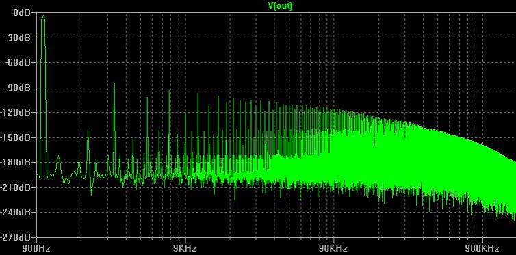
First the THD -
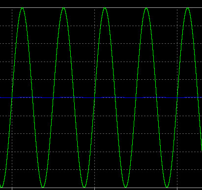
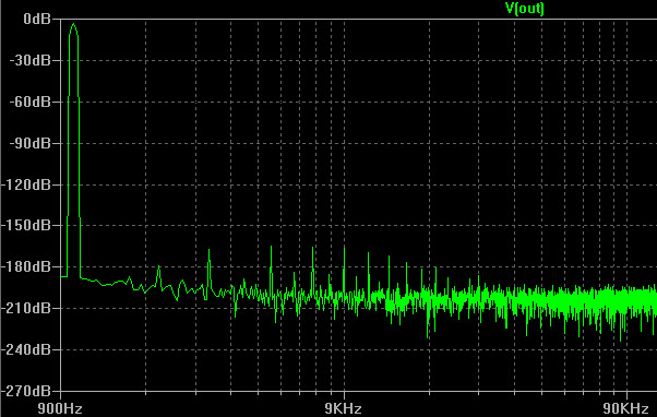
Signal is a 1Khz -6db sine tone. Samling rate is 96Khz.
Without a load I can see just the 2nd and 3rd harmonic but with a load (headphone at normal listening level) this is what happens -

GovibeV6.jpg


I am referring to the harmonics all the way to the end of the spectrum, and especially the rise in harminics towards the end. I know its kind of "out of band" and almost under the 16bit noise floor, but then again Headix's spectrum in contrast is clean all through out. So what about the V6's design or implementation could be causing this hideous (atleast visually) distortion ??


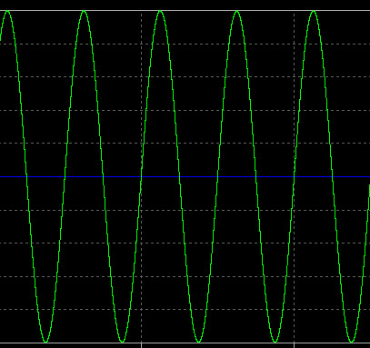
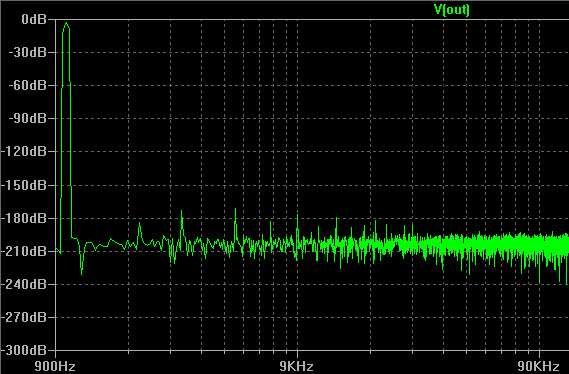
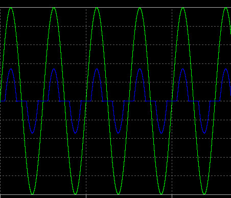
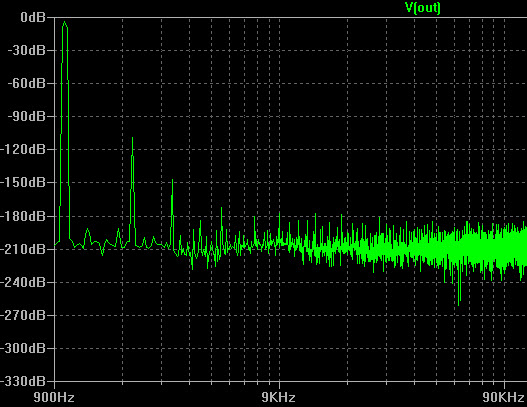
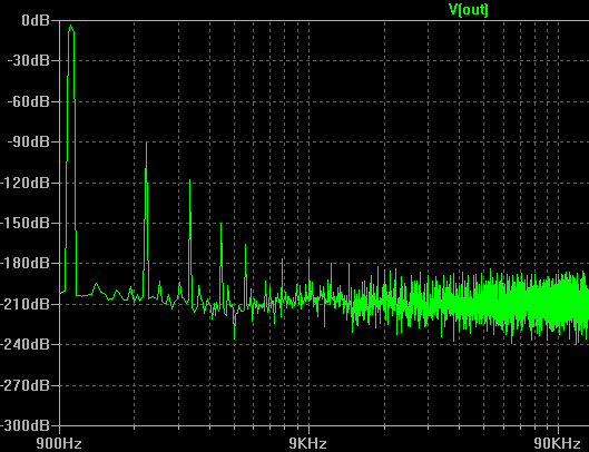
Then the IMD - (60hz + 7Khz sine tone).

GoVibeV6-IMD.jpg


Closeup of IMD -
GoVibeV6-IMDb.jpg


I would expect the IMD harmonic repeated at 14Khz, which is what I see with the Headsix, but in the V6 it repeats all throughout upto the end of the spectrum. Same question - what could be causing this ?
 
May 22, 2009 at 5:45 PM Post #2 of 38
I think you have to show us the result of the soundcard loopback, but it's natural for a class AB amp to show increasing high order distortion under load.
 
May 22, 2009 at 7:54 PM Post #3 of 38
but why would the soundcard loopback results matter when the distortion is not visible when there is no load on the amp itself ? I can post a pic but like I said without a load its just the 2nd and 3rd harmonic - thats it, nothing else.

Keep in mind both the amps use the same chip (well not exactly same but the V6 uses the dual opamp version - AD8620 v/s 10).
 
May 23, 2009 at 9:21 AM Post #4 of 38
Simple...

Active devices (be it transistors, tubes) have non-linear transfer curves. As the voltage across, or current through the device changes due to the music, it ends up operating at different points on its transfer curve (i.e., its transconductance, or gain, changes as a function of the signal). Such non-linearities results in distortion. When the output of an amp is not loaded, only the voltage fluctuates, the current varies little, so the distortion is lower. When you load the output of an amp, the output devices begin to source and sink significant current through the load. Such current changes increase the measured distortion.

Overall negative feedback tends to reduce a lot of the distortions, but it has its vices, especially in a circuit with many stages of amplification (with the resultant poles and zeros added due to junction capacitances).

There are techniques to virtually eliminate these device non-linearities without resorting to very high amounts of overall negative feedback. Namely, full class A operation and dynamic cascoding, which I've employed in every stage of the β22 amp. Class A causes the current through the device to remain relatively constant, and you can tune the quiescent current to be centered around the most linear portion of the device's transfer curve. Dynamic cascoding causes the voltage across the amplifying transistor to become relatively constant, which makes the effective transfer curve very linear, removing much of that source of distortion. Cascoding also effectively removes much of the junction capacitance of a device (the constant voltage across the junctions means no "capacitive charging" effect), which extends the bandwidth and speed.

Unfortunately, these techniques are usually difficult or impossible to "retrofit" to an IC opamp based circuit. You can't modify the circuit within the opamp, and external "class A biasing" doesn't work for driving a headphone or speaker load because the opamp package usually do not have enough power dissipation capacity to allow the high amount of currents for pure class A operation. The power supply of the amp usually isn't adequate either, especially portable amps with battery power.

As for why two different amps based on the same opamp would measure differently, maybe the PCB layout is not optimal on the poorer-performing one, or inadequate supply rail decoupling, or some other issue. It's impossible to know without some hardcore testing and evaluation.
 
May 24, 2009 at 8:23 PM Post #5 of 38
Quote:

As for why two different amps based on the same opamp would measure differently, maybe the PCB layout is not optimal on the poorer-performing one, or inadequate supply rail decoupling, or some other issue.


and thats exactly the purpose of this thread. I am looking forward to discussion on what could be the problem areas.

here are a couple of pictures of the top and bottom of the layouts of both the amps. I don't have a schematic or anything for these amps and haven't visually followed the layout to get an idea of what circuit design they use so can't comment on anything else but seems like supply rails would be a good area to focus on as a starting point.


Top-

amps1.jpg


Bottom -
amps2.jpg
 
May 25, 2009 at 11:15 AM Post #7 of 38
Quote:

Originally Posted by Horse /img/forum/go_quote.gif
The Headsix uses the same opamps only single, AD8610. Guess it doesn't have enough juice as well.

Also 1V on 32 ohm needs 30 mA which the AD8610/20 can deliver comfortably enough (the max. linear output current is 45 mA).


Yes, but at that output and load you can't expect the distortion to be low. It behaves like the class AB amplifier it is.
 
May 25, 2009 at 2:51 PM Post #8 of 38
that is correct, the distortion is visible only in the V6.

the only other major difference I can see, besides the 3-channel approach, is that the Headsix has LOTS of supply rail capacitance - 4000uf v/s 470uf on the V6. Depending on how the capacitance is placed (parallel) that should help with lowering the power supply impedance as well.
 
May 25, 2009 at 4:46 PM Post #9 of 38
Did you use the same battery fully charged in both amps? I guess you did.

I still think it's the opamps not up to the task. You must remember the ground channel AD8610 is sourcing/sinking both L & R channels. I could show you simulations of what happens if you want. Do your measurement at lower volume or with a lighter load to see what happens. You don't have an oscilloscope to see if the amp oscillates or is behaving ill in any other way, do you?
 
May 25, 2009 at 6:05 PM Post #10 of 38
if both channels are driven at the same time for the IMD test then a useful data point could be had by disconnecting one channel's signal or load - cutting in half the current through the active ground channel

another test would be to do a "cross-channel" IMD with only one of the test frequencies in each channel, both driven at once - any IMD product would pretty much have to be coming from the active gnd
 
May 25, 2009 at 6:09 PM Post #11 of 38
yes, same battery in fact. swapped it between amps when testing each.

No I dont have an osilloscope but the chips are not warming up or anything which is usually an indication of oscillation.

sure I would love to see the simulations that you are referring to.

Volume level is at 10' oclock which is typically at or lower than 'normal' listening levels on this amp.
 
May 25, 2009 at 7:41 PM Post #12 of 38
Quote:

Originally Posted by goodsound /img/forum/go_quote.gif
Volume level is at 10' oclock which is typically at or lower than 'normal' listening levels on this amp.


But 1 V test signals aren't a normal input. Have you you ever had the phones on while running the RMAA tests. It's very loud
eek.gif
, and if you listened to music this loud for an extended period you'd destroy your ears.
 
May 25, 2009 at 7:51 PM Post #13 of 38
Here are some exaggerated simulations. A very standard discrete amp with a single push-pull output stage. 1 V output, f = 1 kHz. Class AB biased at 2 mA:

300R load
attachment.php


30R load
attachment.php


Class A biased at 50 mA:

300R load
attachment.php


30R load
attachment.php


May 25, 2009 at 8:12 PM Post #14 of 38
Quote:

Originally Posted by jcx /img/forum/go_quote.gif
if both channels are driven at the same time for the IMD test then a useful data point could be had by disconnecting one channel's signal or load - cutting in half the current through the active ground channel

another test would be to do a "cross-channel" IMD with only one of the test frequencies in each channel, both driven at once - any IMD product would pretty much have to be coming from the active gnd


jcx, looks like our posts crossed.

There is no effect on the amount of distortion in both thd or imd whether only one channel is driven or both.

I did your 'cross channel' imd test. 60hz in the left channel and 7Khz in the right channel, both at 0db. Here are the results -

No Load -
The 7Khz signal was found to be at -80db in the other(left) channel as well.
The 60hz signal was found to be at -60db in the other(right) channel as well.
There were no IMD distortion components to be found.

One channel loaded -
same as above.

Both channels loaded -
same as above + the same IMD distortion as reported in my original post!

I did the same test on the Headsix and once again point to be noted is that this imd distortion is not existent at all in the Headsix. No such thing whatsoever.


So what does this prove ? That the ground channel in the V6 is not isolated enough ?


diditmyself, I am sorry I am not able to see your point. I thought you said something about showing simulations as to how a 3-channel confuguration has an impact of this nature.
 
May 25, 2009 at 8:29 PM Post #15 of 38
This is to exemplify what might be going on in your Go-Vibe when running RMAA tests with a heavy load. When AD8610 is simmed, it starts clipping (current limiting?) at 40R load when the output signal is 1 V so in sim I used 300R as "the light" load and 50R as the heavy load. Green is output and blue is the output ground node. So you see, a clipping ground channel makes a distortion pattern as seen in your RMAA test. Now do the test with a lighter load or lower signal.

I think you can guess which is which.
attachment.php

attachment.php

attachment.php

attachment.php


Users who are viewing this thread

Back
Top