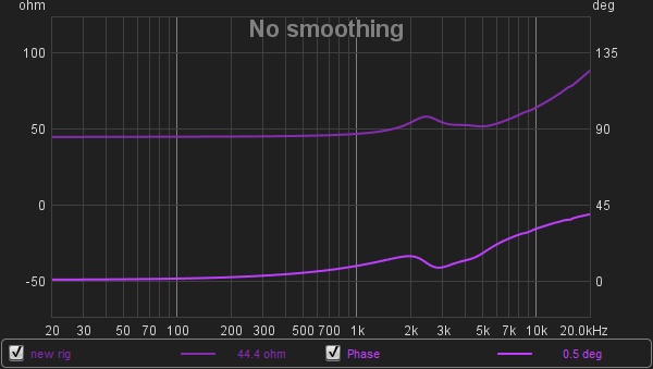
Sorry, if what you care about is the phase measured with the FR, then I'm confidently ignorant. I only remember that for speaker measurements, we want remove the delay in the impulse, to only deal with the typical speaker phase thingy. So with REW maybe you can fool around with that and see if it gives you a more consistent (or expected) result. Not sure what's your level of handling REW, but I would open the pop up "overlay"(at the top and middle of the main window), show "phase" in that pop up. And use the main window to select "impulse"(because that's where you'll have more tools for the impulse). Looking at the impulse you go to "control" on the top right, and you have the "estimate IR delay" that will give you something close to what you should probably want(aligning the impulse with 0second). If that isn't satisfactory, you can always use the "t=0 offset" per sample for fine tuning. That might allow you to get a more realistic phase response, and probably will reduce the massive phase shifts, that you can wrap or not(basically instead of staying in a 360° system, the graph is allowed to wander out to infinity and beyond).
No w obviously all this would probably be much more interesting if you could find a reference somewhere(like a measurement of an IEM you also have, by somebody who really knows his stuff).
I do not know if there is a possibility to separate frequency response from phase shift itself... I don't even know how to say what I mean, not a great sign that I've mastered the subject ^_^. But talking about frequency response having an impact, if you apply some calibration/compensation to the graph, then you can expect it to also modify the phase graph. Maybe also something to check, although if the compensation is a legitimate one, then I imagine the result with it would also be more accurate. This is uneducated guess, I really don't know. I did read about all that long ago when trying to just learn everything about everything, but as soon as I found out that for a listener, frequency response mattered a lot and phase not so much, and often not at all, I just lost interest(yes I'm that lazy).
Now let's hope that somebody knowledgeable will come help you for real, and debunk half of what I just wrote.


