I am sorry if I suggested something too expensive, but at less than $50 including handle and tips it is definitively a bargain for what it offers.I want to declutter my workstation. So I try not too many things and big things on my table. And it’s not cheap for me anyway
You are using an out of date browser. It may not display this or other websites correctly.
You should upgrade or use an alternative browser.
You should upgrade or use an alternative browser.
Home-Made IEMs
- Thread starter Bilavideo
- Start date
hard to admit, but you're right LoLyeah that also.
but seriously, lacquering with a brush is a pain in the ass. no matter how experienced one is. there is always a chance of tiny imperfections. not even talking about the fact that you absolutely need to do it in daylight to not miss small imperfections giving you a chance to retry/adjust before curing. no artificial lights worked as good as daylight thus far for me.
the older the brush is the more tendency it has to catch/create tiny bubbles as well
I have compressor airbrush (aelion pixie) looking for a pen brush that sprays in wide mode, not dot typeyeah that also.
but seriously, lacquering with a brush is a pain in the ass. no matter how experienced one is. there is always a chance of tiny imperfections. not even talking about the fact that you absolutely need to do it in daylight to not miss small imperfections giving you a chance to retry/adjust before curing. no artificial lights worked as good as daylight thus far for me.
the older the brush is the more tendency it has to catch/create tiny bubbles as well
et.haan
100+ Head-Fier
while we are on the topic of lacquer, when in the process do you guys lacquer your shells? Doing it before fixing the drivers cause the lacquer to yellow when the drivers are glued in place.yeah that also.
but seriously, lacquering with a brush is a pain in the ass. no matter how experienced one is. there is always a chance of tiny imperfections. not even talking about the fact that you absolutely need to do it in daylight to not miss small imperfections giving you a chance to retry/adjust before curing. no artificial lights worked as good as daylight thus far for me.
the older the brush is the more tendency it has to catch/create tiny bubbles as well
The reverse is better, but it’s not fun gluing drivers in place while the fitment is not final.
only a matter of cross overi tried TWFK, causes dipping
cannot control its tuning overall

dhruvmeena96
Headphoneus Supremus
Tried 470nF on WBFKonly a matter of cross over
Caused a weird dip at after 4.4kHz
And then resumed its treble
Well, I did cut off the green small connection and wired the WBFK and FK separately
Will see, if that issues persist with normal TWFK
Tulku1967
100+ Head-Fier
- Joined
- Jan 6, 2016
- Posts
- 175
- Likes
- 169
Reverse wiring? (with twfk)Tried 470nF on WBFK
Caused a weird dip at after 4.4kHz
And then resumed its treble
Well, I did cut off the green small connection and wired the WBFK and FK separately
Will see, if that issues persist with normal TWFK
Last edited:
Choy Wei De
100+ Head-Fier
- Joined
- May 16, 2017
- Posts
- 124
- Likes
- 56
I am sorry if I suggested something too expensive, but at less than $50 including handle and tips it is definitively a bargain for what it offers.”
You can offer me a house and a car for 20K. But I simply just cannot afford them.
I get the very good price for that it offers. I can’t afford spending $50 at this point of time for a solder.
ForceMajeure
1000+ Head-Fier
- Joined
- Jan 19, 2014
- Posts
- 1,216
- Likes
- 471
while we are on the topic of lacquer, when in the process do you guys lacquer your shells? Doing it before fixing the drivers cause the lacquer to yellow when the drivers are glued in place.
The reverse is better, but it’s not fun gluing drivers in place while the fitment is not final.
Lacquering is usually done in the last stage after you have assembled everything, everything is finished and everything was already sanded down.
ForceMajeure
1000+ Head-Fier
- Joined
- Jan 19, 2014
- Posts
- 1,216
- Likes
- 471
Tried 470nF on WBFK
Caused a weird dip at after 4.4kHz
And then resumed its treble
Well, I did cut off the green small connection and wired the WBFK and FK separately
Will see, if that issues persist with normal TWFK
try higher value like 1.5uf for the higher part of the twfk and maybe 6.8uf for the lower part of the twfk f.e or you could even use a very high value resistor in front of the lower part if you just want to make it more silent. there are many ways to go about tuning the twfk. but I kinda agree with you that this driver is a bit tricky to control and might not always be worth the hassle.
also tubing plays a role here you'd have to find the correct length to minimize the dip.
et.haan
100+ Head-Fier
Still having issues with the mill, but I tried 3D printing my design for a shell today, and I can say I am quite satisfied with the result, especially for it being a first run through.
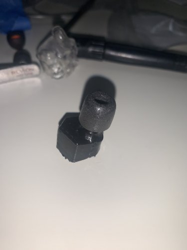
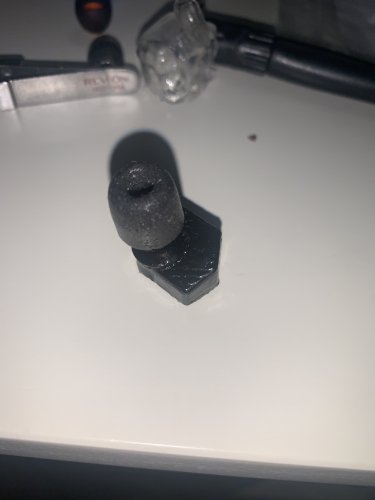
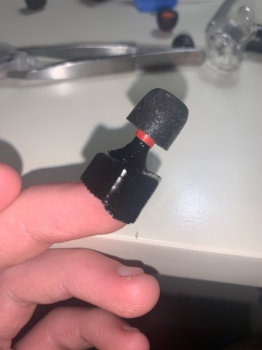
What you cannot see is that despite being set to 95% infill, there is a small area around the base of the snout where it was not properly printed, which I will fix.
Comfort in the ear is good, and there is no pressure anywhere but the ear tip. There is no concha support, although I do plan incorporating this eventually, on a later design.
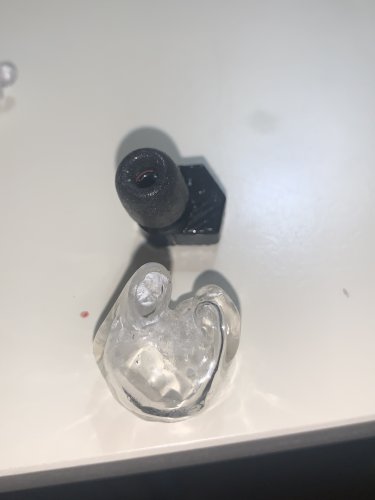
Here it is next to a custom shell
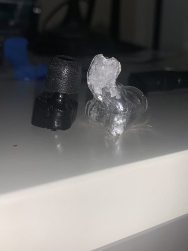
As for the internals, I have work to do. Other than a single driver, it will need a 3D printed driver “tube” setup, like what UE uses. I have heard many people be extraordinarily frustrated with the highly sensitive tuning of Y joints. They can be can be very hard to tune (as in a small change causes a great change in sound). What is great, is that it’s got room! I have room for the sum of BS6 + electronics.
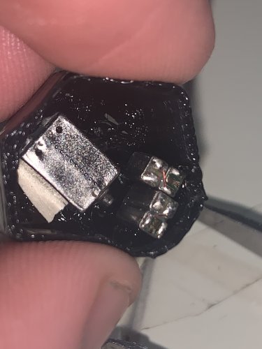
I’ll work on the tube guide for this (BS6 in parts, may be impossible due to resonators, could also be HODVTEC + DWFK + SWFK), as well as 4x RAB/RAF. I am also interested in the weird vented RAF Dhruv was working on. I’ll post these files (with a left version of the shell as well) in a later time. It will have both sides, tube guides, a faceplate and a “farther out of ear” design for prototyping + weird designs. For something like this, I think a guitar pick dremeled to fit is an easy and great faceplate.


What you cannot see is that despite being set to 95% infill, there is a small area around the base of the snout where it was not properly printed, which I will fix.
Comfort in the ear is good, and there is no pressure anywhere but the ear tip. There is no concha support, although I do plan incorporating this eventually, on a later design.
Here it is next to a custom shell


As for the internals, I have work to do. Other than a single driver, it will need a 3D printed driver “tube” setup, like what UE uses. I have heard many people be extraordinarily frustrated with the highly sensitive tuning of Y joints. They can be can be very hard to tune (as in a small change causes a great change in sound). What is great, is that it’s got room! I have room for the sum of BS6 + electronics.

I’ll work on the tube guide for this (BS6 in parts, may be impossible due to resonators, could also be HODVTEC + DWFK + SWFK), as well as 4x RAB/RAF. I am also interested in the weird vented RAF Dhruv was working on. I’ll post these files (with a left version of the shell as well) in a later time. It will have both sides, tube guides, a faceplate and a “farther out of ear” design for prototyping + weird designs. For something like this, I think a guitar pick dremeled to fit is an easy and great faceplate.
Last edited:
Arfan
New Head-Fier
- Joined
- Sep 2, 2011
- Posts
- 24
- Likes
- 13
Just wanna say I'm really impressed by all the work done here, it really is astonishing you guys should be proud. Started out just printing custom shells for my um30s but I'm quite intrigued by this hobby.
I'm just posting because I need some guidance in some research I'm trying to do on CIEMs. I am attempting to write MATLAB code (have a copy through uni) that can simulate what happens to the frequency response (and other parameters of the sound) after it travels from drivers through the tubing. Hopefully doing this we can tune those messy Y connectors and my intention is to SLA print shells with the geometry built in so we can simply plug in the drivers and solder it up, later on moving on to maybe print filters right in there.
Essentially I'm trying to simulate what dhruvmeena96 was doing using sound tubes in parallel and series to tune the sound. I've seen dhruvmeena use COMSOL but I do not have a license or any student version available to use it too ( Although I do have full package of ANSYS which may be able to produce similar results).
Just wondering if its best to use ANSYS or write my own code with MATLAB going forward. The only issue is I'm finding it difficult to find governing equations that describe this phenomenon, anywhere for me to read up on this?
Thanks
dhruvmeena96
Headphoneus Supremus
First of all, you can use anything to code and simulateJust wanna say I'm really impressed by all the work done here, it really is astonishing you guys should be proud. Started out just printing custom shells for my um30s but I'm quite intrigued by this hobby.
I'm just posting because I need some guidance in some research I'm trying to do on CIEMs. I am attempting to write MATLAB code (have a copy through uni) that can simulate what happens to the frequency response (and other parameters of the sound) after it travels from drivers through the tubing. Hopefully doing this we can tune those messy Y connectors and my intention is to SLA print shells with the geometry built in so we can simply plug in the drivers and solder it up, later on moving on to maybe print filters right in there.
Essentially I'm trying to simulate what dhruvmeena96 was doing using sound tubes in parallel and series to tune the sound. I've seen dhruvmeena use COMSOL but I do not have a license or any student version available to use it too ( Although I do have full package of ANSYS which may be able to produce similar results).
Just wondering if its best to use ANSYS or write my own code with MATLAB going forward. The only issue is I'm finding it difficult to find governing equations that describe this phenomenon, anywhere for me to read up on this?
Thanks
Some use CFD(computational Fluid dynamics)
Some use COMSOL( I use crack at home and licensed at office)
Well, that COMSOL is thing of past now. It helped me clear the basics etc.
Now I use pen and paper.
Now I only use it for fluid action or acoustic action simulation
But a MATLAB stuff would be great..
I was working on a software(which is in halt status because of work load) where people can select drivers, calculate dB loss by resistor or L-pad, do crossover
And calculate tube effects etc..
Like a whole program with all the drivers IEC711 response and a graph where you we can mix and match
And then a circuit designer where we can apply circuits and then predict FR
Then going to tube section and then again predicting the shift in response and phase..
Its hard man
I mean literal hard
Arfan
New Head-Fier
- Joined
- Sep 2, 2011
- Posts
- 24
- Likes
- 13
First of all, you can use anything to code and simulate
...
Then going to tube section and then again predicting the shift in response and phase..
Its hard man
I mean literal hard
Yeah I can second that. I'm currently using ANSYS workbench with CFX/Fluent for a CFD project atm at university so I may look into using this. The one thing about the internal flow is I guess it can be modelled quite well in simply 2D due to the scale we're at with CIEMs. Good thing about this is it means that anyone can do it, ANSYS offer a student version of their workbench that allows enough elements for use with 2D flows.
Might be useful for anyone getting into this as from first glance it is a bit more user friendly than COMSOL, although maybe not in implementing the results.
I'll get back to you guys about what I come up with though. And my reshells of the um30s are nearly done. Can't wait.
dhruvmeena96
Headphoneus Supremus
1- COMSOL is more user friendly comparing to ANSYS. It provides more tools in easier way to use comparing to ANSYS. For example, COMSOL has predefined CAD geometries such as Bolt, which is unique in FEA software, you may just find such tool in SolidWorks. COMSOL is more easily for multiphysics modelling comparing to ANSYS which lots of times you need coding and other labors for multiphysics  .
.
2- COMSOL has some physics which you may not find even find in ANSYS, such as solute transport. These pro is very important in multiphysics modelling when you are going to solve a coupled model with very different physics.
3- COMSOL provides you the ability to define your own PDE and equation
Doing same thing is god level hard on ANSYS
You will start using COMSOL in future
ANSYS is good for learning
But not great for research and prototyping
 .
.2- COMSOL has some physics which you may not find even find in ANSYS, such as solute transport. These pro is very important in multiphysics modelling when you are going to solve a coupled model with very different physics.
3- COMSOL provides you the ability to define your own PDE and equation
Doing same thing is god level hard on ANSYS
You will start using COMSOL in future
ANSYS is good for learning
But not great for research and prototyping
Users who are viewing this thread
Total: 8 (members: 0, guests: 8)


