Home-Made IEMs
Oct 9, 2015 at 5:12 PM Post #3,931 of 15,989
   
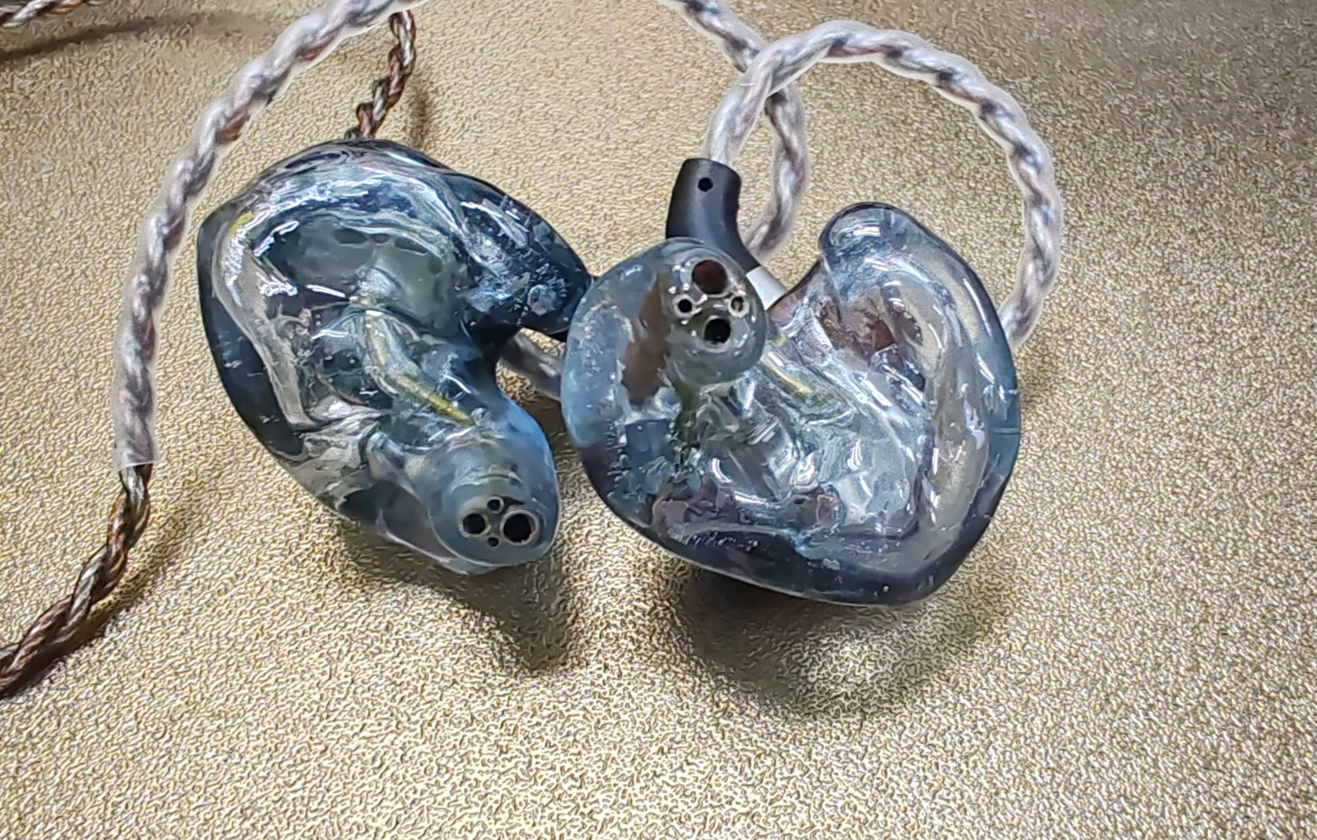
Nice!! I see you used MMCX connectors of which I'm a big fan.  I also some components in there other than the drivers.  Did you separate the TWFK and the CI from the GK's crosover so you could position the TWFK down into the canal?  That's pretty smart!  Some have complained about trying to put double tubes on the GK but because of the lack of clearance between the two nozzles, it's a pain.  
 
I'm thinking Peter's idea is going to do away with the existing crossover and suggest a 3-way, or maybe just add a 2nd order LP crossover to one of those CIs. Either way, a TWFK + 2 CI's has the making of one hell of a great sounding IEM.  Can't wait!

 
Yup! I took the cables from an old pair of Shures that I had and didn't want to invest in another set of cables, so I used MMCX connectors. They seem to be more durable than the two-pin connectors anyways. 
 
I did separate the TWFK from the GK - it was a matter of sliding a razor blade between the two drivers. The epoxy they use to hold them together is quite tough! I had to clean the GK's CI off before I could stick the other CI on it. Like I said before, my ears and ear canals are tiny as heck so I had to find a way to make things work. :) But with the second CI on it, I still had to deal with the double nozzle issue but sticking a single #12 tube on it wasn't any more difficult than the stock GK setup.
 
I can't really tell what the crossover that Knowles puts on the GK is - it seems like a first-order crossover of a resistor and a capacitor, but I can't tell which driver it is cutting without slicing the circuit board off the GK, which I'm less willing to do. :p
 
The bass of a double CI combo has been really good - I've been mostly listening to the bass of dynamic drivers and so I wanted the same impact that dynamics have. It is almost to that level, but I'm not sure if there's some resonance issues but the bass and lower mids are a little muddy. But the muddiness might also be because the TWFK isn't providing the air that it usually would. 
 
 
As a side note, in making the shells, I've found that cleaning any tacky residue from the shell (I used UV nail gel) with acetone is a much better option than using a glycerin bath to do a post-cure of the shells. Using a glycerin post-cure seems to cause random strands of acrylic to cure in random places, resulting in the gritty texture of my shells. I actually peeled off a few layers of acrylic from the inside of my shell because it post-cured while glycerin was underneath and so there was a very thin flat air bubble along the shell. It also once caused the shells to seal themselves shut (with glycerin inside) because the leftover acrylic floated to the top of the shell and cured there. Leaving the tack for cleaning with a bit of acrylic leaves a much cleaner and smoother surface.
 
Oct 9, 2015 at 5:44 PM Post #3,932 of 15,989
OK guys,
 
here's the "cool" project... ("super cool" will have to wait till it's measured, because I don't want to put up something that doesn't work)
The design below is quite easy (took me 5min to sketch and it's pretty much bullet proof if you wire it correctly - as in the picture).
 
First of all I figured if @pc27618349 is using GK why not reuse parts from it, and since the GK is using 22uF cap and the idea is for more neutral sound we can allow for higher resistor lower cap combo for lowpass.
Secondly I provided you with two possible resistor values and cap values to have a bit of wiggle room if you want to add small changes without throwing everything out of order. The same goes for tubing and damper values.
 
Finally, if R1 value goes up TWFK output will increase, so by increasing R1 you not only move cut off slope back to the left on graph but also decrease the output in that range relative to 1kHz.
If the sound is still too bass-heavy you can put R2 of 20-40Ohms on the second CI (the one w/o lowpass). This will "speed-up" the bass, lower the CI's output and increase relative TWFK's output.
 
Happy tuning!
 
[Eidt] The above design turned a bit flawed so please go the post http://www.head-fi.org/t/430688/home-made-iems/3960#post_12019755 for correct wiring and second more fancy 4way design. Sorry.
 
Oct 9, 2015 at 5:47 PM Post #3,933 of 15,989
I think initially a lot of us love the deep dark bass that dynamic drivers provide. I haven't had luck getting that same sound from BA's and I slowly became ok with that and began to appreciate the bass I was hearing even though it's different than what I was used to. I haven't heard any high end IEMs so maybe you can achieve that subwoofer type bass.

I'm sure the GK crossover question has already been answered already on this forum as to which driver is being x-overed and what the crossover frequency is.

About your tack layer on your shells, I never had this problem that you are describing. It almost sounds like you did the initial cure, the brushed on another coat of gel, put it in glycerine then tried to cure it. That's wrong. You need to do a long cure first to try and catalyze as much of the acrylic as possible before you put it in glycerine. If you're trying to cure a fresh wet layer of gel in the glycerine, you'll definitely run into problems you have described. It did that once or twice and after much cursing, learned that lesson the hard way. What kind of UV light are you using? A handheld LED flashlight or some UV bulb setup? I use both.

Acetone will certainly strip off that tick layer as well as the cured layer. It's powerful stuff. I use isopropyl alcohol but unfortunately both acetone and isopropyl alcohol can leave the surface cloudy which is astetically unpleasing to some. You can get a really nice shine by doing your final coat in gloss and then curing that tack layer in glycerine. At least that's what I do and it's worked pretty well.


Yup! I took the cables from an old pair of Shures that I had and didn't want to invest in another set of cables, so I used MMCX connectors. They seem to be more durable than the two-pin connectors anyways. 

I did separate the TWFK from the GK - it was a matter of sliding a razor blade between the two drivers. The epoxy they use to hold them together is quite tough! I had to clean the GK's CI off before I could stick the other CI on it. Like I said before, my ears and ear canals are tiny as heck so I had to find a way to make things work. :) But with the second CI on it, I still had to deal with the double nozzle issue but sticking a single #12 tube on it wasn't any more difficult than the stock GK setup.

I can't really tell what the crossover that Knowles puts on the GK is - it seems like a first-order crossover of a resistor and a capacitor, but I can't tell which driver it is cutting without slicing the circuit board off the GK, which I'm less willing to do. :p

The bass of a double CI combo has been really good - I've been mostly listening to the bass of dynamic drivers and so I wanted the same impact that dynamics have. It is almost to that level, but I'm not sure if there's some resonance issues but the bass and lower mids are a little muddy. But the muddiness might also be because the TWFK isn't providing the air that it usually would. 


As a side note, in making the shells, I've found that cleaning any tacky residue from the shell (I used UV nail gel) with acetone is a much better option than using a glycerin bath to do a post-cure of the shells. Using a glycerin post-cure seems to cause random strands of acrylic to cure in random places, resulting in the gritty texture of my shells. I actually peeled off a few layers of acrylic from the inside of my shell because it post-cured while glycerin was underneath and so there was a very thin flat air bubble along the shell. It also once caused the shells to seal themselves shut (with glycerin inside) because the leftover acrylic floated to the top of the shell and cured there. Leaving the tack for cleaning with a bit of acrylic leaves a much cleaner and smoother surface.
 
Oct 9, 2015 at 5:53 PM Post #3,934 of 15,989
  As a side note, in making the shells, I've found that cleaning any tacky residue from the shell (I used UV nail gel) with acetone is a much better option than using a glycerin bath to do a post-cure of the shells. Using a glycerin post-cure seems to cause random strands of acrylic to cure in random places, resulting in the gritty texture of my shells. I actually peeled off a few layers of acrylic from the inside of my shell because it post-cured while glycerin was underneath and so there was a very thin flat air bubble along the shell. It also once caused the shells to seal themselves shut (with glycerin inside) because the leftover acrylic floated to the top of the shell and cured there. Leaving the tack for cleaning with a bit of acrylic leaves a much cleaner and smoother surface.

After first curing and pouring out uncured material, place it under UV for a 2-3min, then remove the shell from your negative form (avoid touching surface with fingers, use some tweezers) and then place it glycerin and then post-cure for 2-3more minutes. That should solve your problem and should leave no tacky residue.
 
Oct 9, 2015 at 6:11 PM Post #3,936 of 15,989
@piotrus-g , did you mean to wire those CI in reverse polarity? I'm sure you did but just wanted confirmation.

Yes! + and - near the tap is the polarity of the driver and + and - near the wire is polarity of signal
 
BTW. If you check where the CI pads are on my scheme or where the vent on TWFK is the scheme is pretty much easy - just make sure you positioned the back of the drivers for soldering as on my scheme, and you'll be good to go.
 
Oct 9, 2015 at 11:18 PM Post #3,938 of 15,989
Originally Posted by Furco /img/forum/go_quote.gif
 
 
Agreed!  That youtube video was very helpful for me to illustrate the effects of a delay in signals.  As you have said, even at 0.5ms, the delay was obvious.   So can we come up with a rule-of-thumb that says something such as:  "Configurations that result in a delay (lag or lead) of 10µs (microseconds) or larger will cause coherence problems and should be remediated in multi-driver configurations."  How exactly to deal with the delays remains to be seen.  So if we go back to your example where there's an 83.3µs (0.0833ms) delay caused by a 1st order HP crossover in a multi-driver configuration, that's a problem based on our new rule-of-thumb.   So if 10µs is our theoretical lower limit, I wonder how the frequency response would look  between your example configuration and one where the phase was corrected .   Interesting.....interesting.....interesting.......  I'll have to think about how to test this.  


 I think there is a way to measure phase in the ARTA software bundle. It includes LIMP, same kind of software as arta that can measure Impedance and Phase of headphone just by running it into some kind of "JIG" made of a simple resistor. That's how ti looks like 
 
.
Originally Posted by Furco /img/forum/go_quote.gif

This is starting to get a little sticky.  Earlier, I was okay with the concepts about delay being measured in "time" and how that affects the coherence of sound.  Now, we're starting to introduce phase shifts measured in degrees and how that can affect the harmonics .  I'm okay with understanding both "delay" and "phase shifts" as separate and independent influences but now we have to merge the two into a single definition.
--Cheers

It is not as complicated as it sounds. Phase shift is just a way to represent a time difference between two waves in deg so it can be shown on graphs where the horizontal line is time and vertical line is amplitude (deciblels in our case).  Simple explanation here https://www.youtube.com/watch?v=OKsmqzRFFsk
 
Also if you play the guitar here is a great video explaining phases in pickups that also illustrate part cancellation. https://www.youtube.com/watch?v=jzghyYl7_60
 
Oct 10, 2015 at 12:07 AM Post #3,939 of 15,989
  Yes! + and - near the tap is the polarity of the driver and + and - near the wire is polarity of signal
 
BTW. If you check where the CI pads are on my scheme or where the vent on TWFK is the scheme is pretty much easy - just make sure you positioned the back of the drivers for soldering as on my scheme, and you'll be good to go.

Question:
1. Do you connect the unfiltered Ci driver to the filtered one directly in reverse polarity so the Low Pass filter is for both CI's simultaneously, if so wouldn't they be cancelling out each other completely?
2. Or do you connect the unfiltered CI driver in reverse polarity before the low pass circuit of the filtered one so it "kinds of play" with the filtered CI Frequency response by partially adding/or cancelling part of the overall response.
I hope you understand what I mean..
 
Also thank you very much for sharing this design.
Just by looking at this, if the response for my question is 2, it just open so much more possibilities in term of tuning I never thought about. It is like you could play with different values of resistors and caps with two of the same drivers(or even different drivers) and alter the part of the frequency response you want to.
even invert one driver's polarity so you can get some kind slight cancellation or addition of frequencies in the bass or mid or treble area (depending of the  RC filter/or /dampers and band part you are working on)
and not knowing the flip polarity effect just by some kind of "educated trial and error" could stumble in a desired sound...
 
I hope you understand what I mean...
 
Oct 10, 2015 at 3:13 AM Post #3,940 of 15,989
 I think there is a way to measure phase in the ARTA software bundle. It includes LIMP, same kind of software as arta that can measure Impedance and Phase of headphone just by running it into some kind of "JIG" made of a simple resistor. That's how ti looks like.


I believe that's electrical phase, what furco was referring to was acoustical phase.
 
Oct 10, 2015 at 4:16 AM Post #3,941 of 15,989
I believe that's electrical phase, what furco was referring to was acoustical phase.

You are right, I thought that it measured acoustical phase but it is electrical phase,is there a way to measure the acoustical phase in arta? 
Or do we need those very expensive scopes to measure it?
 
Well at least it can measure the impedance that's nice.
 
Oct 10, 2015 at 4:37 AM Post #3,942 of 15,989
Did you want the CI's wired with reverse parity to cut down on their SPL so they're not drowning out the twfk?

No, otherwise they would cancel TWFK and mess up the phase.
  Question:
1. Do you connect the unfiltered Ci driver to the filtered one directly in reverse polarity so the Low Pass filter is for both CI's simultaneously, if so wouldn't they be cancelling out each other completely?
2. Or do you connect the unfiltered CI driver in reverse polarity before the low pass circuit of the filtered one so it "kinds of play" with the filtered CI Frequency response by partially adding/or cancelling part of the overall response.
I hope you understand what I mean..
 
Also thank you very much for sharing this design.
Just by looking at this, if the response for my question is 2, it just open so much more possibilities in term of tuning I never thought about. It is like you could play with different values of resistors and caps with two of the same drivers(or even different drivers) and alter the part of the frequency response you want to.
even invert one driver's polarity so you can get some kind slight cancellation or addition of frequencies in the bass or mid or treble area (depending of the  RC filter/or /dampers and band part you are working on)
and not knowing the flip polarity effect just by some kind of "educated trial and error" could stumble in a desired sound...
 
I hope you understand what I mean...

I'm not sure I understood your questions completely so if I don't answer what you are asking about, feel free to ask more.
1. Low pass is working for only one CI in the scheme above. You want both CI in the same polarity with each other. Otherwise they will cancel bass frequencies. You could definitely do:
 so the Low Pass filter is for both CI's simultaneously

But I would design it differently - I would wire CI in series via low pass filter. FK section of TWFK in full range or by big cap like 20-40uF and WBFK section of TWFK with capacitor around 1uF. However I would expect it to create unwanted dip at 3-5kHz due to phase canceling.
 
2. You want both unfiltered and filtered CI in the same polarity. Some designers do what you asked about. Mainly such design would look something like HODVTEC in full range + DTEC+high ohm resistor in reversed polarity. Such design would result in moderate midrange level - think ~110dB@500Hz, and lift in sub-bass Think ~115dB@100Hz. While wiring them in the same polarity would result in say 125dB@100Hz and 128dB@500Hz (ok, I'm pulling those numbers out of my @$$ but you get the idea I hope). So as you see matching tweeter to 125dB or more is PITA really - you'd need like 3xTWFK to do this.
Personally I don't like such wiring (in opposite polarity) it messes mid-range in my opinion. Your brain receives two opposite information in range that your ear is highly sensitive and basically tries to make anything out of it. Sound is a bit echo-y and slightly unsettling.
 
Oct 10, 2015 at 6:27 AM Post #3,943 of 15,989
Ok I think I understand what you mean.
 
Is this the way you meant for connecting your original design ? 

If so what is the benefit of connecting both CI in reverse polarity?
 
 
  No, otherwise they would cancel TWFK and mess up the phase.
I'm not sure I understood your questions completely so if I don't answer what you are asking about, feel free to ask more.
1. Low pass is working for only one CI in the scheme above. You want both CI in the same polarity with each other. Otherwise they will cancel bass frequencies. You could definitely do:
But I would design it differently - I would wire CI in series via low pass filter. FK section of TWFK in full range or by big cap like 20-40uF and WBFK section of TWFK with capacitor around 1uF. However I would expect it to create unwanted dip at 3-5kHz due to phase canceling.
 

Is this how it should look like? Also am I right about the FK and WBFK part? Is it how it should be wired?


2. You want both unfiltered and filtered CI in the same polarity. Some designers do what you asked about. Mainly such design would look something like HODVTEC in full range + DTEC+high ohm resistor in reversed polarity. Such design would result in moderate midrange level - think ~110dB@500Hz, and lift in sub-bass Think ~115dB@100Hz. While wiring them in the same polarity would result in say 125dB@100Hz and 128dB@500Hz (ok, I'm pulling those numbers out of my @$$ but you get the idea I hope). So as you see matching tweeter to 125dB or more is PITA really - you'd need like 3xTWFK to do this.
Personally I don't like such wiring (in opposite polarity) it messes mid-range in my opinion. Your brain receives two opposite information in range that your ear is highly sensitive and basically tries to make anything out of it. Sound is a bit echo-y and slightly unsettling.

 What is the difference between the HODVTEC and the DTEC drivers. Is the HODVTEC just a vented DTEC? Why can't I find any info on it in the knowles website?
Can I trust the graphs on this datasheet for the HODVTEC?
 
Also are the graph in this datasheet for the DTEC accurate especially the rising part from 500hz to 1000hz of about 10db? Are there good drivers that can be used for lowmids to highmids/highs with a nice steady rise from ~200hz to 1000hz of about 4db ?
 
Oct 10, 2015 at 7:18 AM Post #3,944 of 15,989
  Ok I think I understand what you mean.
 
Is this the way you meant for connecting your original design ? 

If so what is the benefit of connecting both CI in reverse polarity?
 
 
Is this how it should look like? Also am I right about the FK and WBFK part? Is it how it should be wired?


 What is the difference between the HODVTEC and the DTEC drivers. Is the HODVTEC just a vented DTEC? Why can't I find any info on it in the knowles website?
Can I trust the graphs on this datasheet for the HODVTEC?
 
Also are the graph in this datasheet for the DTEC accurate especially the rising part from 500hz to 1000hz of about 10db? Are there good drivers that can be used for lowmids to highmids/highs with a nice steady rise from ~200hz to 1000hz of about 4db ?

The first scheme is correct. Yes.
The second would look like this: sorry for my paint skills

 If so what is the benefit of connecting both CI in reverse polarity?

As I mentioned before - no phase canceling with TWFK.
 What is the difference between the HODVTEC and the DTEC drivers. Is the HODVTEC just a vented DTEC? Why can't I find any info on it in the knowles website?

Yup it's vented DTEC (High Output Dual Vented TEC ?) http://www.knowles.com/eng/Applications/Specialty-components/Hearing-aid-components/Balanced-Armature-Products datasheet: http://www.knowles.com/eng/content/download/5924/103192/version/7/file/Receiver+Datasheet+HODVTEC-31618-000.pdf
 Can I trust the graphs on this datasheet for the HODVTEC?

Yes
 Also are the graph in this datasheet for the DTEC accurate especially the rising part from 500hz to 1000hz of about 10db? Are there good drivers that can be used for lowmids to highmids/highs with a nice steady rise from ~200hz to 1000hz of about 4db ?

This graph is done in different conditions (BTE - hearing aid - setup)
.
Here's DTEC 30008 measured in the same conditions as HODVTEC above


Users who are viewing this thread

Back
Top