


StillaStillsFan
New Head-Fier
- Joined
- Mar 8, 2008
- Posts
- 21
- Likes
- 1
[size=24.0pt]High-Quality Stax Headphone Adapter[/size]
[size=20.0pt]By [/size]
[size=20.0pt]Don Roth and [/size][size=18.0pt]Birgir Guðjónsson[/size]
[size=12.0pt]This project allows one to build a very high quality version of the Stax SRD-7MkII headphone adapter to allow one to use an existing favorite amplifier to power your stax headphones. (Let Birgir know what amplifier you have to find out if the adapter is possible in your setup.) If you can find a used SRD-7MkII, which are pretty rare, it likely would be less expensive (~$300??) than the project adapter. But because this project uses high quality parts (mainly the James Transformers, Teflon insulation silver coated wiring, and silver solder), you might achieve superior sound quality. I have had a SRD-7MkII and I believe subjectively that the project adapter achieves superior channel separation, instrument isolation, detail and bass quality.[/size]
[size=12.0pt]Included below is a complete parts list. Total parts cost is about $400 - $500. I don’t have the receipts for a few parts but I estimated the cost on those.[/size]
[size=12.0pt]I only added a normal bias stax connector since I use the wonderful Stax Lambda Normal headphones. But the circuit board allows connection for both normal and high (pro) bias, and one could easily cut another hole in the chassis for another Stax headphone connector so that you can have both possibilities available like the SRD-7MkII does.[/size]
[size=12.0pt]It took me about 4 months to build working as time permitted. I think that this could be finished in a week or less if one has the dedicated time. I’ve been using this for nine months with perfect operation. Thanks so much to Birgir for his help throughout the project. Please feel free to comment and suggest improvements.[/size]
[size=22.0pt]Parts List[/size][size=22.0pt]:[/size]
Stax SRD-7-MkII circuit board equivalent from Birgir Guðjónsson, Comes with optional red LED. My version came with red LED, $110.
[size=14.0pt]Wire Parts List:[/size]
14 ga Silver-coated wire (Teflon-insulation I think) for Speaker Circuit and what I have been using as speaker wire for many years (bought from Scott Welbourne many years ago)
20 ga multi-stranded Teflon-insulated wire for headphone circuit (from a friend)
Romex wire for power circuit (Home Depot)
[size=14.0pt]MCM Electronics Part List:[/size]

[size=14.0pt]Newark Electronics Part List:[/size]
[size=12.0pt](This very expensive and very heavy duty switch to switch between headphones and loudspeakers allowed use of 14 gauge speaker wire.)[/size]

[size=12.0pt]Here is an alternate lower duty part which will work fine and was originally used.[/size]
[size=14.0pt]Mouser Electronics Parts List:[/size]

[size=14.0pt]Allied Electronics Part List:[/size]
[size=12.0pt]Stax Normal connector[/size]

[size=14.0pt]Tctubes Vintage Vacuum Tubes Parts List:[/size]

[size=14.0pt]Radio Shack Parts List:[/size]
SPST Power Rocker Switch, catalog# 275-0693, 125VAC-10A (250VAC-6A), $3.19
Screw Cap Panel-Mount Fuse Holder, catalog# 270-364, 250VAC-10A, $2.19
0.5A 250V Fast-Acting 1¼x¼" Glass Fuse (4-Pack), catalog#: 270-1003, $2.19
Female Insulated Crimp-on Quick Disconnects, catalog# 64-4039, 5 each 1/4”, 1/16” 22-18 gauge, $2.19
[size=14.0pt]Miscellaneous Parts List:[/size]
Flux for electrical soldering (non-corrosive and non-conductive), $5
Spare circuit board material, ~$2
SparVar Indoor/Outdoor Spray Paint, part# S110 Glossy Black, 11oz. can ~$3
Kinkos Print Shop – custom labels, ~$10
Isolation Transformer purchased off of Ebay to eliminate AC power hum

(As Birgir says below, future boards will be manufactured with small hum isolation transformers)
Rubber chassis feet (bumpers from Home Depot), $3.00
½” – 1” standoffs and screws for such for mounting Stax SRD-7-MkII circuit board equivalent (hardware store), $0.50
[size=22.0pt]Tools[/size][size=22.0pt]:[/size]
Needle Nose Pliers
Jeweler (slot head) and regular Screw driver
Drill, Drill Press (with various bits) (alternate would be set of metal punches).
Metal Punch or hole saw
Dremel cutting tool with metal cutting discs
Pencil and paper, scissors, exacto knife
[size=22.0pt]Building the Adapter[/size][size=22.0pt]:[/size]
[size=12.0pt]Here is a circuit diagram for the SRD-7MkII circuit:[/size]

[size=12.0pt]The circuit provides the voltages required at the various pins of the headphone connector for the Stax headphones to work properly.[/size]
[size=12.0pt]The circuit is based around a voltage multiplier (six stages) with a limited input voltage. The supply takes the AC mains voltage from the wall, limits to 100V and then steps it up six times and rectifies it in the process. Now the circuit uses virtually no power at all but in case of a short the high impedance nature of the voltage multiplier will make the output voltage fall well short of the 600VDC so this is very safe in practice. The output is also fed through a 5Mohm resistor so in case of a short the voltage will be reduced even further. [/size]
[size=12.0pt]The supply also has spots for a voltage divider on the output of the multiplier which allows for output for virtually any electrostatic headphone. The voltage can be cut down to 230V for the normal bias Stax models (done in the case of this article), 540V for the Sennheiser HE60, 500V for the Sennheiser Orpheus or 180V for the Beyer Dynamic ET-1000. [/size]
[size=12.0pt]The supply being connected directly to the mains and not through an isolation transformer isn’t ideal but it had to be done so that these boards would fit in the old Stax SRD line of adapter boxes. This setup can cause hum issues so I would recommend a small isolation transformer (4VA is plenty) between the IEC input and the boards. Next version of the boards will have built in transformers but that will have to wait until I (Birgir) run out of the current version of the boards. [/size]
[size=12.0pt]On the latest version of the supply I also added a small circuit that allows the use of LED’s for power indication. Stax used neon bulbs in their boxes which work just fine off the high AC voltages but LED’s need much lower voltages. Neon NE-2 bulbs can still be used but the LED’s look much better. [/size]
[size=12.0pt]For the normal bias, the connections on the headphone connector are:[/size]

[size=12.0pt]For the pro bias, the connections on the headphone connector are: [/size]

[size=12.0pt]And a picture of the connector itself showing proper mounting orientation:[/size]

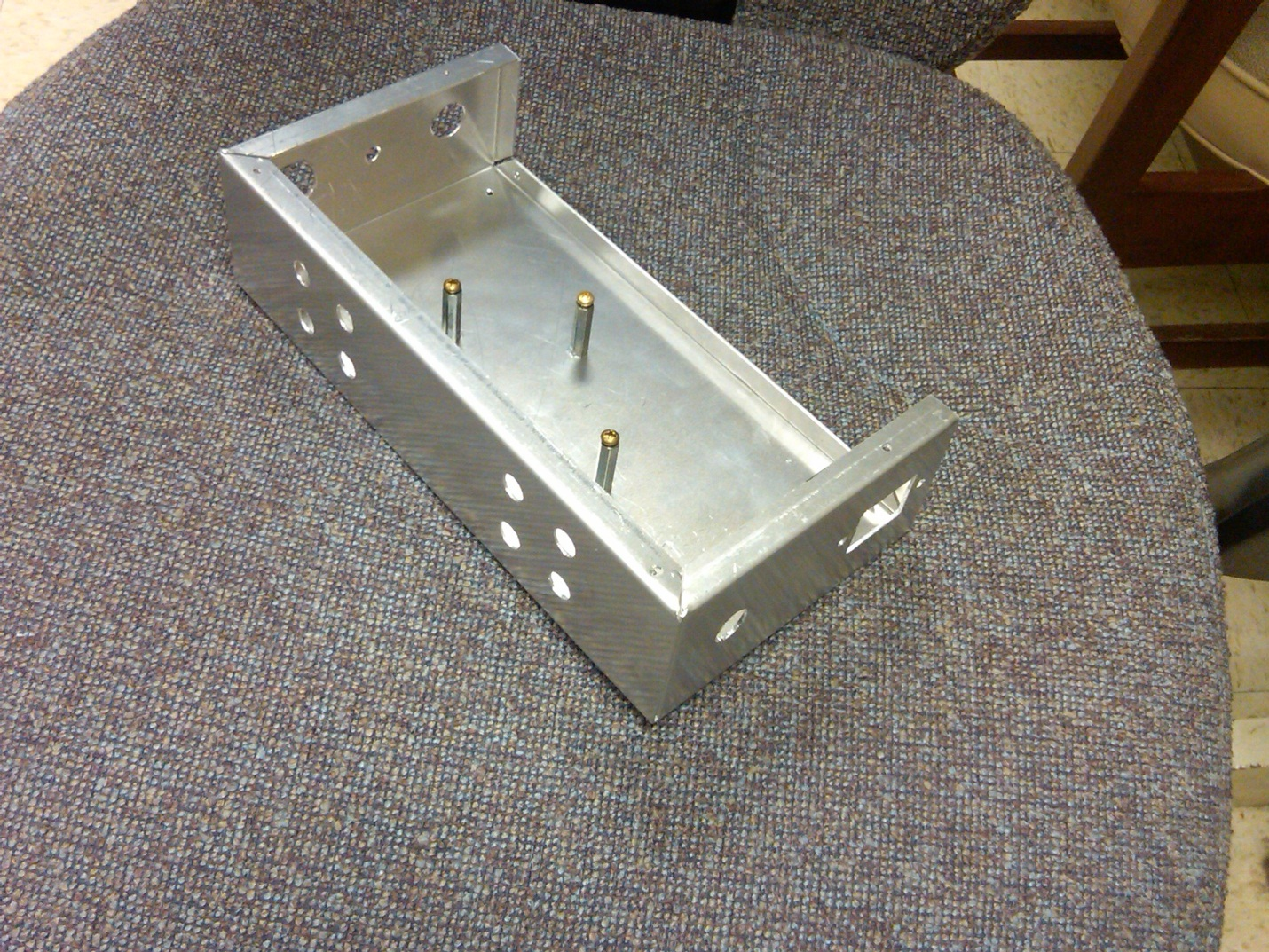
[size=12.0pt]The first step in the project is to measure the positions for and make all of the holes in the aluminum chassis for the parts to be mounted. Some of the packaging for the parts provides measurements for the proper hole size to drill. Create a template out of paper and lay out the holes on the chassis for each side depending on how you want everything placed. For those parts that don’t have defined drill sizes, one can measure the part itself or place it against the paper and trace it out. We did our best to center things both vertically and horizontally to create a professional-looking chassis. The following two photos show some example templates:[/size]


[size=12.0pt]Trace the holes with a pencil. Use an exacto knife and scissors to cut out the holes in the paper, and tape the paper to the chassis. Studying the various photographs to follow, you will see more clearly how we placed everything on the three sides of the chassis utilized.[/size]
[size=12.0pt]The holes can be drilled with metal-cutting drill bits by hand or using a drill press. Smaller holes can also be punched with a set of metal punches. The large holes for the transformers can be punched if one has access to a professional metal punch or drilled out using a hole saw. A dremel tool with cutting disc and a file can be used to cut the approximately rectangular hole for the AC power socket. File down any sharp edges.[/size]
[size=12.0pt]Chassis with holes made (and standoffs for board mounted) (bottom):[/size]

[size=12.0pt]Chassis with holes made (for transformers) (top):[/size]

[size=12.0pt]After the chassis holes are made, prior to painting, test mount the parts to make sure the holes are correct. [/size]
[size=12.0pt]Then, the chassis can be painted. I highly recommend the paint in the parts list I show. You will not need a primer and it seems very durable. I sprayed on three coats, letting paint dry between coats. The circuit board material I used as an insulator on both the interior and exterior of the chassis became almost unnoticeable on the exterior after the spray coats. Then, start mounting all of the connectors for the final assembly.[/size]
[size=12.0pt]Here are some photos of the interior of the chassis after making the holes, painting, and mounting some of the parts:[/size]
[size=12.0pt]Back side (interior view):[/size]

[size=12.0pt]Front side (interior view):[/size]

[size=12.0pt]Full interior view after mounting board:[/size]

[size=12.0pt]Input/Output Terminals Exterior View (later switched red nuts with black nuts as red should be on top):[/size]

[size=12.0pt]After mounting the transformers on the top of the chassis and mounting the SRD7-MkII board on standoffs on the chassis:[/size]
[size=12.0pt]Interior Views (top and bottom parts of chassis)[/size]

[size=12.0pt]James transformer pins and their connection to the rest of the project:[/size]

[size=12.0pt]Here I started the wiring (soldering not started yet). I ran all of the wires before beginning to solder. The input/output connectors require a very small slot head screwdriver to attach the wires, and no soldering is required. Romex black strand was used for the power circuit. 20 gauge multistrand Teflon-insulated wire was used initially for sound signal circuit. Later when I went to the heavy duty 4PDT switch with screw terminals for the headphone/loudspeaker switch, I inserted 14 gauge silver-coated wire that I use to connect my speakers.[/size]

[size=12.0pt]There are two bias outputs on the PCB, both in the upper right hand corner. One is labeled PRO and that outputs around 580VDC and is for use with the Stax Pro bias headphones. The second output is labeled VD (voltage divider) and that can be configured for any number of voltages. If the board didn’t come preset from me then there is a small table on the PCB with the recommended resistor values for 230V and 500V (Stax normal bias and Sennheiser Orpheus) output. If the board was preset then there is a small marking on the PCB in the lower right hand corner where I’ve written the voltage divider output voltage. [/size]
[size=12.0pt]Close-up of wired Stax connector:[/size]

[size=12.0pt]Close-up of wired transformers:[/size]

Here is where I put in the new 4PDT switch so I could use the 14 gauge wire in the sound signal circuit. This switch also used screw terminals for attachment rather than soldering. I had to remove the old switch and drill a larger hole. I labeled all the wires prior to removing the old switch. I applied flux to all joints prior to soldering. Flux is a chemical cleaner which removes oxidation from metal surfaces so that a good solder-to-metal bond can be made. A silver solder was used.
[size=12.0pt]Here is an interior view of the new 4PDT switch showing the screw terminals within the yellow-dashed-line circle. You can see how much larger this switch is than the original I had used.[/size]

[size=12.0pt]Before closing everything up on the adapter, I tested it using a spare receiver since I wanted to make sure it worked before inserting into my actual system:[/size]

[size=12.0pt]Here are a few photos of the (close to) finished product. [/size]
[size=12.0pt]I had Kinkos print shop make labels for me for all of the switches and connectors. In normal light, the black background of the labels blends well into the black spray-painted chassis.[/size]


[size=12.0pt]And here it is in the system. I am a big fan of HH Scott and the modified version of the 222-d integrated amp shown is an excellent match for the Stax headphones and Altec 19 Voice of the Theatre speakers that I own. [/size]

[size=12.0pt] [/size]
[size=20.0pt]By [/size]
[size=20.0pt]Don Roth and [/size][size=18.0pt]Birgir Guðjónsson[/size]
[size=12.0pt]This project allows one to build a very high quality version of the Stax SRD-7MkII headphone adapter to allow one to use an existing favorite amplifier to power your stax headphones. (Let Birgir know what amplifier you have to find out if the adapter is possible in your setup.) If you can find a used SRD-7MkII, which are pretty rare, it likely would be less expensive (~$300??) than the project adapter. But because this project uses high quality parts (mainly the James Transformers, Teflon insulation silver coated wiring, and silver solder), you might achieve superior sound quality. I have had a SRD-7MkII and I believe subjectively that the project adapter achieves superior channel separation, instrument isolation, detail and bass quality.[/size]
[size=12.0pt]Included below is a complete parts list. Total parts cost is about $400 - $500. I don’t have the receipts for a few parts but I estimated the cost on those.[/size]
[size=12.0pt]I only added a normal bias stax connector since I use the wonderful Stax Lambda Normal headphones. But the circuit board allows connection for both normal and high (pro) bias, and one could easily cut another hole in the chassis for another Stax headphone connector so that you can have both possibilities available like the SRD-7MkII does.[/size]
[size=12.0pt]It took me about 4 months to build working as time permitted. I think that this could be finished in a week or less if one has the dedicated time. I’ve been using this for nine months with perfect operation. Thanks so much to Birgir for his help throughout the project. Please feel free to comment and suggest improvements.[/size]
[size=22.0pt]Parts List[/size][size=22.0pt]:[/size]
Stax SRD-7-MkII circuit board equivalent from Birgir Guðjónsson, Comes with optional red LED. My version came with red LED, $110.
[size=14.0pt]Wire Parts List:[/size]
14 ga Silver-coated wire (Teflon-insulation I think) for Speaker Circuit and what I have been using as speaker wire for many years (bought from Scott Welbourne many years ago)
20 ga multi-stranded Teflon-insulated wire for headphone circuit (from a friend)
Romex wire for power circuit (Home Depot)
[size=14.0pt]MCM Electronics Part List:[/size]
[size=14.0pt]Newark Electronics Part List:[/size]
[size=12.0pt](This very expensive and very heavy duty switch to switch between headphones and loudspeakers allowed use of 14 gauge speaker wire.)[/size]
[size=12.0pt]Here is an alternate lower duty part which will work fine and was originally used.[/size]
[size=14.0pt]Mouser Electronics Parts List:[/size]
[size=14.0pt]Allied Electronics Part List:[/size]
[size=12.0pt]Stax Normal connector[/size]
[size=14.0pt]Tctubes Vintage Vacuum Tubes Parts List:[/size]
[size=14.0pt]Radio Shack Parts List:[/size]
SPST Power Rocker Switch, catalog# 275-0693, 125VAC-10A (250VAC-6A), $3.19
Screw Cap Panel-Mount Fuse Holder, catalog# 270-364, 250VAC-10A, $2.19
0.5A 250V Fast-Acting 1¼x¼" Glass Fuse (4-Pack), catalog#: 270-1003, $2.19
Female Insulated Crimp-on Quick Disconnects, catalog# 64-4039, 5 each 1/4”, 1/16” 22-18 gauge, $2.19
[size=14.0pt]Miscellaneous Parts List:[/size]
Flux for electrical soldering (non-corrosive and non-conductive), $5
Spare circuit board material, ~$2
SparVar Indoor/Outdoor Spray Paint, part# S110 Glossy Black, 11oz. can ~$3
Kinkos Print Shop – custom labels, ~$10
Isolation Transformer purchased off of Ebay to eliminate AC power hum
(As Birgir says below, future boards will be manufactured with small hum isolation transformers)
Rubber chassis feet (bumpers from Home Depot), $3.00
½” – 1” standoffs and screws for such for mounting Stax SRD-7-MkII circuit board equivalent (hardware store), $0.50
[size=22.0pt]Tools[/size][size=22.0pt]:[/size]
Needle Nose Pliers
Jeweler (slot head) and regular Screw driver
Soldering Station, e.g. Temperature Controlled ESD Analog Solder Station, 120V / 60 Watts, with 42W Iron.
Drill, Drill Press (with various bits) (alternate would be set of metal punches).
Metal Punch or hole saw
Dremel cutting tool with metal cutting discs
Pencil and paper, scissors, exacto knife
[size=22.0pt]Building the Adapter[/size][size=22.0pt]:[/size]
[size=12.0pt]Here is a circuit diagram for the SRD-7MkII circuit:[/size]
[size=12.0pt]The circuit provides the voltages required at the various pins of the headphone connector for the Stax headphones to work properly.[/size]
[size=12.0pt]The circuit is based around a voltage multiplier (six stages) with a limited input voltage. The supply takes the AC mains voltage from the wall, limits to 100V and then steps it up six times and rectifies it in the process. Now the circuit uses virtually no power at all but in case of a short the high impedance nature of the voltage multiplier will make the output voltage fall well short of the 600VDC so this is very safe in practice. The output is also fed through a 5Mohm resistor so in case of a short the voltage will be reduced even further. [/size]
[size=12.0pt]The supply also has spots for a voltage divider on the output of the multiplier which allows for output for virtually any electrostatic headphone. The voltage can be cut down to 230V for the normal bias Stax models (done in the case of this article), 540V for the Sennheiser HE60, 500V for the Sennheiser Orpheus or 180V for the Beyer Dynamic ET-1000. [/size]
[size=12.0pt]The supply being connected directly to the mains and not through an isolation transformer isn’t ideal but it had to be done so that these boards would fit in the old Stax SRD line of adapter boxes. This setup can cause hum issues so I would recommend a small isolation transformer (4VA is plenty) between the IEC input and the boards. Next version of the boards will have built in transformers but that will have to wait until I (Birgir) run out of the current version of the boards. [/size]
[size=12.0pt]On the latest version of the supply I also added a small circuit that allows the use of LED’s for power indication. Stax used neon bulbs in their boxes which work just fine off the high AC voltages but LED’s need much lower voltages. Neon NE-2 bulbs can still be used but the LED’s look much better. [/size]
[size=12.0pt]For the normal bias, the connections on the headphone connector are:[/size]
[size=12.0pt]For the pro bias, the connections on the headphone connector are: [/size]
[size=12.0pt]And a picture of the connector itself showing proper mounting orientation:[/size]
[size=12.0pt]The first step in the project is to measure the positions for and make all of the holes in the aluminum chassis for the parts to be mounted. Some of the packaging for the parts provides measurements for the proper hole size to drill. Create a template out of paper and lay out the holes on the chassis for each side depending on how you want everything placed. For those parts that don’t have defined drill sizes, one can measure the part itself or place it against the paper and trace it out. We did our best to center things both vertically and horizontally to create a professional-looking chassis. The following two photos show some example templates:[/size]
[size=12.0pt]Trace the holes with a pencil. Use an exacto knife and scissors to cut out the holes in the paper, and tape the paper to the chassis. Studying the various photographs to follow, you will see more clearly how we placed everything on the three sides of the chassis utilized.[/size]
[size=12.0pt]The holes can be drilled with metal-cutting drill bits by hand or using a drill press. Smaller holes can also be punched with a set of metal punches. The large holes for the transformers can be punched if one has access to a professional metal punch or drilled out using a hole saw. A dremel tool with cutting disc and a file can be used to cut the approximately rectangular hole for the AC power socket. File down any sharp edges.[/size]
[size=12.0pt]Chassis with holes made (and standoffs for board mounted) (bottom):[/size]
[size=12.0pt]Chassis with holes made (for transformers) (top):[/size]
[size=12.0pt]After the chassis holes are made, prior to painting, test mount the parts to make sure the holes are correct. [/size]
[size=12.0pt]Then, the chassis can be painted. I highly recommend the paint in the parts list I show. You will not need a primer and it seems very durable. I sprayed on three coats, letting paint dry between coats. The circuit board material I used as an insulator on both the interior and exterior of the chassis became almost unnoticeable on the exterior after the spray coats. Then, start mounting all of the connectors for the final assembly.[/size]
[size=12.0pt]Here are some photos of the interior of the chassis after making the holes, painting, and mounting some of the parts:[/size]
[size=12.0pt]Back side (interior view):[/size]
[size=12.0pt]Front side (interior view):[/size]
[size=12.0pt]Full interior view after mounting board:[/size]
[size=12.0pt]Input/Output Terminals Exterior View (later switched red nuts with black nuts as red should be on top):[/size]
[size=12.0pt]After mounting the transformers on the top of the chassis and mounting the SRD7-MkII board on standoffs on the chassis:[/size]
[size=12.0pt]Interior Views (top and bottom parts of chassis)[/size]
[size=12.0pt]James transformer pins and their connection to the rest of the project:[/size]
[size=12.0pt]Here I started the wiring (soldering not started yet). I ran all of the wires before beginning to solder. The input/output connectors require a very small slot head screwdriver to attach the wires, and no soldering is required. Romex black strand was used for the power circuit. 20 gauge multistrand Teflon-insulated wire was used initially for sound signal circuit. Later when I went to the heavy duty 4PDT switch with screw terminals for the headphone/loudspeaker switch, I inserted 14 gauge silver-coated wire that I use to connect my speakers.[/size]
[size=12.0pt]There are two bias outputs on the PCB, both in the upper right hand corner. One is labeled PRO and that outputs around 580VDC and is for use with the Stax Pro bias headphones. The second output is labeled VD (voltage divider) and that can be configured for any number of voltages. If the board didn’t come preset from me then there is a small table on the PCB with the recommended resistor values for 230V and 500V (Stax normal bias and Sennheiser Orpheus) output. If the board was preset then there is a small marking on the PCB in the lower right hand corner where I’ve written the voltage divider output voltage. [/size]
[size=12.0pt]Close-up of wired Stax connector:[/size]
| |
[size=12.0pt]Close-up of wired transformers:[/size]
Here is where I put in the new 4PDT switch so I could use the 14 gauge wire in the sound signal circuit. This switch also used screw terminals for attachment rather than soldering. I had to remove the old switch and drill a larger hole. I labeled all the wires prior to removing the old switch. I applied flux to all joints prior to soldering. Flux is a chemical cleaner which removes oxidation from metal surfaces so that a good solder-to-metal bond can be made. A silver solder was used.
|
[size=12.0pt]Here is an interior view of the new 4PDT switch showing the screw terminals within the yellow-dashed-line circle. You can see how much larger this switch is than the original I had used.[/size]
[size=12.0pt]Before closing everything up on the adapter, I tested it using a spare receiver since I wanted to make sure it worked before inserting into my actual system:[/size]
[size=12.0pt]Here are a few photos of the (close to) finished product. [/size]
| |
[size=12.0pt]I had Kinkos print shop make labels for me for all of the switches and connectors. In normal light, the black background of the labels blends well into the black spray-painted chassis.[/size]
[size=12.0pt]And here it is in the system. I am a big fan of HH Scott and the modified version of the 222-d integrated amp shown is an excellent match for the Stax headphones and Altec 19 Voice of the Theatre speakers that I own. [/size]
[size=12.0pt] [/size]

