bmwpowere36m3
100+ Head-Fier
- Joined
- Aug 17, 2008
- Posts
- 274
- Likes
- 3
*BUILD DONE*
I completed my build of the CMoY, it took a few hours since it was my first DIY amp build and I strayed from the original plans. All in all I'm happy with the build, after using it for a while on 2x 9V, I switch over to a DC wall-wart and to accompany it I added a THREAD.
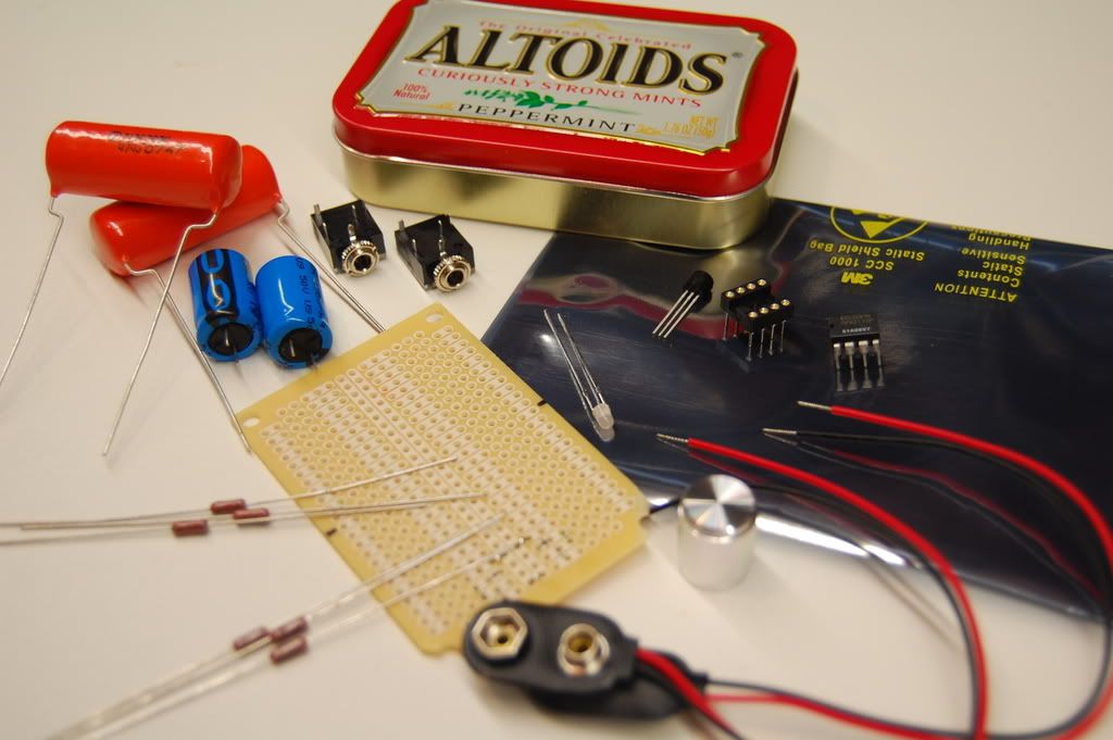
Here are the parts:
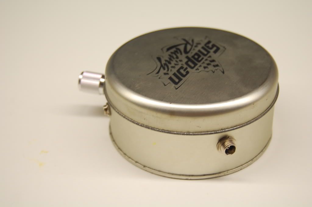
Here's the completed amp:
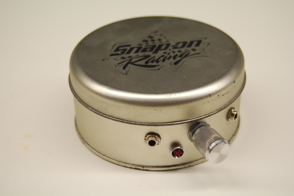
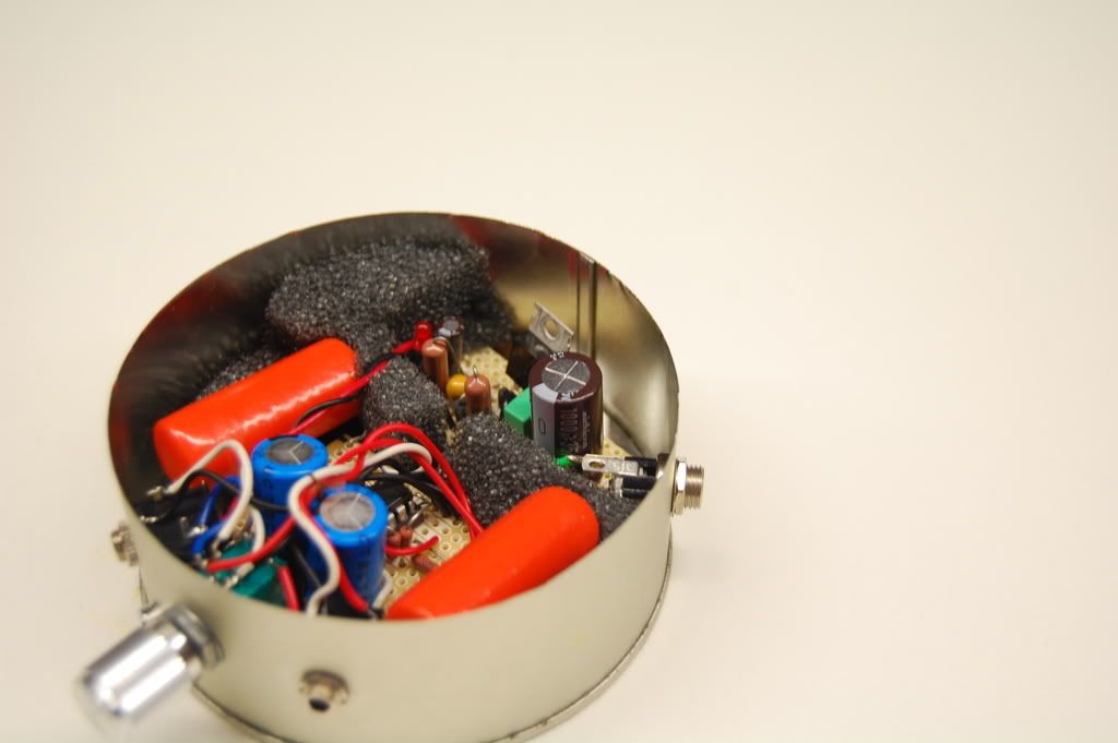
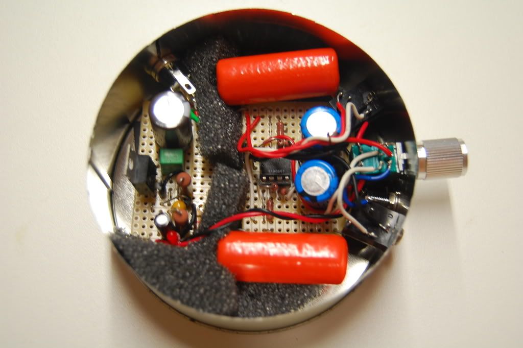
I initially wanted to build the amp into an Altoids tin. With future possibilities of running in on battery power and plugged-in @ home to conserve power. I made one huge oversight during the build, when I chose to use larger caps (both the PS 470uf and coupling .47uF ones) I didn't account for their size. There was no way they would fit in the Altoids tin and upon initial build w/ the dual 9V batteries I realized I never use this as a portable amp... so I switched over to a THREAD and added a wall-wart.
*Initial Proposition*
After some more research and decision making I've finally come up with my game plan for my CMoY build. Here's my list of parts ordered thru Newark:
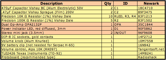
Parts in salmon are the "original" components based on tangentsoft.net and the yellow ones are my own choice.
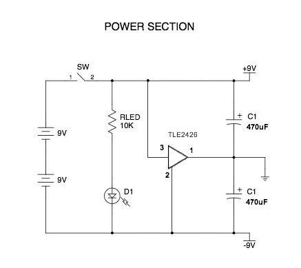
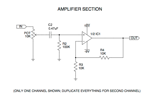
Here's the schematic:
All that's left is to get some protoboards and an altoids tin...
I got the itch to build a headphone amplifier and decided a cmoy is a nice first start. I will only be powering IEM's with this amp, (Shure E2's, RE2, and YUIN PK3). I've decided to use this tutorial: How to Build the CMoy Pocket Amplifier
I've decided to go with a gain of 2 due to IEM usage. Now my question is does this look good (i'll be getting the protoboard and 3.5mm jacks @ RS unless there one's on Digikey as well?).
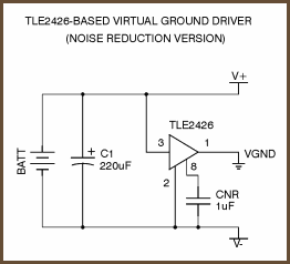
I was thinking of adding a buffer virtual ground, the "TLE2426-Based Virtual Ground (Noise Reduction Version), now my question is what the additional capacitor (CNR 1uF), is it actually 1uF? Is this virtual ground improvement even worth it?
Finally can I run on 1x 9V battery or should I go with 2x? Any other tips and hints would be appreciated, thanks.
I completed my build of the CMoY, it took a few hours since it was my first DIY amp build and I strayed from the original plans. All in all I'm happy with the build, after using it for a while on 2x 9V, I switch over to a DC wall-wart and to accompany it I added a THREAD.
Here are the parts:
Here's the completed amp:
I initially wanted to build the amp into an Altoids tin. With future possibilities of running in on battery power and plugged-in @ home to conserve power. I made one huge oversight during the build, when I chose to use larger caps (both the PS 470uf and coupling .47uF ones) I didn't account for their size. There was no way they would fit in the Altoids tin and upon initial build w/ the dual 9V batteries I realized I never use this as a portable amp... so I switched over to a THREAD and added a wall-wart.
*Initial Proposition*
After some more research and decision making I've finally come up with my game plan for my CMoY build. Here's my list of parts ordered thru Newark:
Parts in salmon are the "original" components based on tangentsoft.net and the yellow ones are my own choice.
Here's the schematic:
All that's left is to get some protoboards and an altoids tin...
I got the itch to build a headphone amplifier and decided a cmoy is a nice first start. I will only be powering IEM's with this amp, (Shure E2's, RE2, and YUIN PK3). I've decided to use this tutorial: How to Build the CMoy Pocket Amplifier
I've decided to go with a gain of 2 due to IEM usage. Now my question is does this look good (i'll be getting the protoboard and 3.5mm jacks @ RS unless there one's on Digikey as well?).
I was thinking of adding a buffer virtual ground, the "TLE2426-Based Virtual Ground (Noise Reduction Version), now my question is what the additional capacitor (CNR 1uF), is it actually 1uF? Is this virtual ground improvement even worth it?
Finally can I run on 1x 9V battery or should I go with 2x? Any other tips and hints would be appreciated, thanks.


