Help troubleshooting CTH build
May 24, 2009 at 8:32 PM Thread Starter Post #1 of 52

arteom

1000+ Head-Fier
Joined
Sep 5, 2006
Posts
1,357
Likes
149
Hello, I am having trouble powering up my CTH, would like to let it be know that I am a bit of a DIY noob. Here is the story so far:

I recently ordered a CTH kit from Bill and went ahead to populate the board, all things seemed to go fine with a few snags here and there (mostly components placed in wrong slot), but I fixed those problems as I went along. I got near the end and had a big setback, I had installed the 47u 50v cap in the C3H slot, I thought I had followed the instruction on Alex's site, but later as I went back to it to find out what the 330u 50v cap was now highlighted in yellow and set to be in C3H. So I took the old cap out and put the new one in. For whatever idiotic reasons I had cut the leads before putting C3H in, and fear that I had cut them too short, but at this point I was optimistic that I had not.

At this point the Board powered up fine, the bi-colored LED turned green after a few moments and stayed as such after some repeated power-ups. However the problem was with the heater, tubes were glowing too hot, the heater switch had no effect on the unit. Using a 12AU7A the tube would get pretty hot after about 30 seconds and would be lighting up a bit too much, using a 6DJ8 tube would cause the tube to glow like a light bulb. I was not getting correct reading on pins 1 and 6.

I too removed the C3H cap and did indeed find that one of the leads was bent in and likely not making good contact (although I was not sure as it might have been making contact with solder that was pulled out when the 47u cap was taken off). What I did was took some leads and ran them through C3H and soldered them to the C3H cap. Being the noob that I am I accidentally hit both the leads of the power cap next to C3H, this caused some sparks to fly but the cap looks to be in good shape and from what I understand it only discharged when this happened, what I fear is that it discharged into some of the components near it. The reason I fear this is because now the LED is not turning on at all. If I place a tube in it will light up as before, but again with the LED not turning on at all.

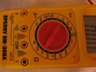
I would really appreciate help in figuring this out, I have a digital multimeter and am ready to take some readings.
 
May 24, 2009 at 10:54 PM Post #2 of 52
If you suspect the heater circuit is not putting out the proper voltage, just measure voltage on tube socket pins 4 & 5 (with or without a tube in).

R1H & R3H control the voltage the heater switcher puts out, so if you don't get 12.6V on tube pins 4 & 5 with heater switch off, I'd inspect them.

But that was before the sparks. When you say LED does not light at all, you mean not GREEN & not RED, right?

There are a series of setup tests here, but I think we should 1st find out if you've got 24V coming out of the 24V reg. The output pin of your 24V reg (7824 - ICP) is the one toward the front of the board... The one marked "O" on the PCB. So measure from center pin to "O" pin & then from center pin to "I" pin & let us know the values.

If you do get about 32V in & 24V out, then maybe proceed with those setup tests & let us know any "bad" values.
 
May 24, 2009 at 11:24 PM Post #3 of 52
Yeah, not green or red, used to light green.

From center to "o" it measures 0 volts, from the center to "I" it starts at 1 volt and settles at about .3 volts.

I will inspect the resistors but first would like to get that light back on.

Thanks for the help!
 
May 24, 2009 at 11:57 PM Post #4 of 52
The light is not important right now. It sounds like you fried the transistors for the capacitance multiplier, hopefully.

The power section is made up of 3 separate circuits that live on it's own. There's only 1 tie-in point to that, actually 2. Ground and the source 24V AC.

First, please make sure your transformer is outputting something. It should be a tad higher than 24VAC.

Second, measure relative to SG, the voltage at R1P, toward the top right of the board in the picture here. What is the value?

Third, measure relative to SG the voltage at the test point TB+, then at pins 1 and 6 of the empty tube socket and note what they are.

Fourth, measure the voltage at pins 4 and 5 of the empty tube socket and toggle the heater voltage switch to see if it changes, and if so, to what.

If all is good, continue on with the startup steps.
 
May 25, 2009 at 12:10 AM Post #5 of 52
Measuring from the power in hot to SG I get a reading of 13.2 volts. Did I measure it correctly?

From SG to R1P I get a reading of 42.8v

From SG to TB+ I get a reading of 110.6v

Tb+ to pin 1 I get 0v, Tb+ to pin 6 I get 74.5v, Pin 4 = .9v pin 5 = 110.6

I have for the time being removed the wiring for the heater switches, I hope you don't mind me skipping the last step. I want to first focus on getting the amp on (green light on). If it is important or if you would just rather have me do it let me know and I will rewire the heater switch.

Thanks!
 
May 25, 2009 at 12:18 AM Post #6 of 52
Quote:

Originally Posted by arteom /img/forum/go_quote.gif
Measuring from the power in hot to SG I get a reading of 13.2 volts. Did I measure it correctly?

From SG to R1P I get a reading of 42.8v

From SG to TB+ I get a reading of 110.6v

Tb+ to pin 1 I get 0v, Tb+ to pin 6 I get 74.5v, Pin 4 = .9v pin 5 = 110.6

I have for the time being removed the wiring for the heater switches, I hope you don't mind me skipping the last step. I want to first focus on getting the amp on (green light on). If it is important or if you would just rather have me do it let me know and I will rewire the heater switch.

Thanks!


Measure all the tube pins with respect to SG.

SO with the black probe on SG, measure voltages at the pins of the tube.

Donot measure with respect to Tb+.

Also measure the voltages (DC mode) at the outer pins of ICP with respect to SG (black probe on SG).
 
May 25, 2009 at 12:26 AM Post #8 of 52
please measure pin1 and pin6 relative to SG.

please measure pin4 and pin5 relative to SG.

Your AC adapter is in AC, not DC. I don't think you measured it correctly, but it's not necessary now. It's working.

Q1P and Q2P are probably dead if you're measurement of the 24V rail is showing 0. To further identify which of the transistors, you can do a diode test on the transistors as follows.

Put the red cable of your DMM (in diode test mode) on the middle pin of the transistor. That is the base. Put the black cable of your DMM (in diode test mode) on 1 of the other pins (C or E), it should measure ~0.7V. Put the black cable of your DMM on the last pin. It should measure ~0.7v too. Reverse the cables and they should measure 0V. If any of those don't measure correctly, that is the bad transistor. It could be (Q1P) or (Q2P) or (Q1P and Q2P).

The BC550C datasheet to help you identify B C and E more readily.
 
May 25, 2009 at 12:28 AM Post #9 of 52
Quote:

Originally Posted by arteom /img/forum/go_quote.gif
Oh, Sorry

ok, from SG to pin 1 = 0v, pin 6 = 36.3v, pin 4 = 109.7, pin 5 = 0v


pin4 = 109.7v? Impossible.

You're measuring it backwards. pin1 is on the other side.
smily_headphones1.gif
The pins count in a counter-clockwise manner.

Edit: Your pin 4 measurement is really pin6, and looks OK for a socket without a tube. TB+ is working, just need measurement at pin1 to confirm that side is OK as well. It should be about the same.
 
May 25, 2009 at 12:51 AM Post #10 of 52
*facepalm

well that shows just how much of a noob I am

now to do it correctly
smily_headphones1.gif
. SG to pin 1 = 109.4v, pin 6 = 109.3v, pin 4 = 36.1v, pin 5 = 0v

If I am correct on setting this up for diode test mode on transistor Q1P I got readings of .7 and 1, would this be the bad transistor? On Q2P I got .7 and .7, I am unsure of what you mean by "Reverse the cables and they should measure 0V." Do you mean put the black cable on base and red on pins?

Also, kind of embarrassing to ask but might anyone verify that I have the DMM setup correctly for diode test mode? I turned the dial to what I have highlighted in green and plugged into the ohm and comm ports.

IMG_01361-1.jpg
 
May 25, 2009 at 12:54 AM Post #11 of 52
hmmm..looks like you might have a malfunctioning ICH, the LM2595 is probably dead. Don't put in a tube until you change ICH and see 12.6 volts or thereabouts on pin4 with respect to SG..

The other values seem a tad high but are ok.
 
May 25, 2009 at 1:24 AM Post #12 of 52
Quote:

Originally Posted by arteom /img/forum/go_quote.gif
SG to pin 1 = 109.4v, pin 6 = 109.3v, pin 4 = 36.1v, pin 5 = 0v


Looks good on pin1 and pin6. The voltage will drop down once current flows through a tube. Pin4 is way too high, as Sachu already noted.

Quote:

Originally Posted by arteom /img/forum/go_quote.gif
If I am correct on setting this up for diode test mode on transistor Q1P I got readings of .7 and 1, would this be the bad transistor? On Q2P I got .7 and .7,


Yes, it looks like Q1P is bad from that reading, but you must reverse the leads to be 100% sure.

Quote:

Originally Posted by arteom /img/forum/go_quote.gif
I am unsure of what you mean by "Reverse the cables and they should measure 0V." Do you mean put the black cable on base and red on pins?


Bingo. An NPN transistor is modeled as 2 diodes with the band pointing away from the base. B->E, and B->C. If you get forward voltage going from C->B and/or E->B with the diode test, it's bad.

Quote:

Originally Posted by arteom /img/forum/go_quote.gif
I turned the dial to what I have highlighted in green and plugged into the ohm and comm ports.


I *think* that is correct. The best way to verify would be to RTFM.
smily_headphones1.gif
 
May 25, 2009 at 1:28 AM Post #13 of 52
Hmm, so I should go ahead and order a ICH and Q1P? Also do feel like an idiot for letting this happen again (would think I would learn the lesson from the first time), but while re-measuring Q1P I shorted one of the leads to the ICP, I think I may have fried it and will order another. But do you guys think it might have damaged something else? I should really get some adapters for the DMM as I am using the standard tips with it. Hopefully this happening twice is enough to teach me to take extra care when working in such tight spaces.

Thanks for all the help guys!
 
May 25, 2009 at 2:10 AM Post #14 of 52
more or less correct.

For the ICH, double check the pin readings.

LM2595 Datasheet

Double check the resistors as well, to make sure none have blown.

Edit: Your 24V reg may have died too, but there's no way to tell short of feeding it a 28V DC or higher value in a test circuit. You may want to contact wiatrob about the parts, I'm sure his shipping is cheaper than shipping orders from Digikey and/or Mouser in large-ish boxes for bit parts.
 
May 25, 2009 at 2:16 AM Post #15 of 52
you may also want to double check the buffer transistors. Particularly the pair on the output for each side. It's possible that something could have gone through and toasted something further down the line as well.

Be prepared to have to make multiple orders because you may fix something to find something else down the line is dead. That's just the way it is for DIY life.
 

Users who are viewing this thread

Back
Top