Help me come up with potential mods for my DAC
Jun 8, 2007 at 5:59 PM Thread Starter Post #1 of 21

Illah

1000+ Head-Fier
Joined
Sep 9, 2004
Posts
1,332
Likes
12
How do you know you're an audio nerd? When you're considering mods for a DAC you don't even have yet
biggrin.gif


I just ordered a Silverstone EB-01 last night and it should be here Monday. I'm not an electronics whiz so I'm just wondering what mods might be possible with this little guy.

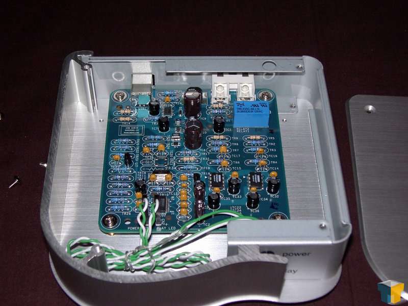
Here's a semi-high rez pic I found online. Already I can see the opamps on the lower right-hand side. Not sure specifically which opamps they are, but that's an easy point for potential upgrading. They're not socketed but look easy enough to desolder (and maybe add sockets for easy swapping). Anything else pop out to you guys?

--Illah

silverstone_eb01_7.jpg
 
Jun 8, 2007 at 6:09 PM Post #2 of 21
It's hard to tell, but it looks like those op amps might be Burr Brown OPA something, so there's a good chance theyre good to begin with. I'm liking the layout on that thing. Almost entirely through hole, instead of SMD that I would assume to be cheaper to manufacture.

Edit: Actually, it looks like the DAC IC could be a Burr Brown too.

Edit 2: Wow, I googled around a bit, and apparently it uses a PCM2702, which is the same DAC used in many DIY projects, like the Alien DAC. It also uses OPA604 opamps, which are also quite good. At $100, this could be a great alternative for people who don't want to deal with DIYing things.

Edit 3: As far as possible mods go, it's USB powered (5v), so you're somewhat limited in terms of what op amps you could switch for. Most of the resistors are already metal film; it's likely those carbon ones aren't in the signal path (or they were specifically chosen to be). The best you could probably do is switching out caps. It looks like Silverstone did a good job designing this thing.
 
Jun 8, 2007 at 6:54 PM Post #4 of 21
Yeah, off with those opamps, and start socketing
wink.gif


Tangent compared the opa604 with some others (http://www.tangentsoft.net/audio/opamps.html). he says they sound similar to the opa2132. I think the opa2132 is utter crap, at least not audiophile by any means.
What I find strange is that the opa604 requires at least 9v rail-to-rail power, so there must be some dc-dc converter in it
confused.gif

Have you got some higher res pics?

Anyways, going with an AD8065, OPA627, AD8610, OPA228 might be a good way to tweak.

Another tweak is bypassing the usb power supply. Just cut the power lines on the usb cable, and make for example a TREAD 5v power supply. The power over the usb cable is often noisy, not well suited for high grade audio equipment attached to it.

edit: I have to agree with spongezone. Looks well built overall. There's even a relay close to the output, thank god they didn't use transistors there.

You could also look if there are caps directly in the signal path. You could switch these with some polypropylenes.
C32, C33, C35 and the one with the number not visible next to them are likely the power reservoir caps of the opamps, while the orange caps next to them are the tantalum(or are they ceramics??) bypass caps. Room for improvement there as well. You could switch them (the electrolytics I mean) with higher capacity, low esr ones. You could leave the tantals, or replace them with high grade ceramic decoupling caps (ok, that might be a bit over the top).

And of course, the two big caps in the upper middle could be even bigger, meaning also replacing them with some low esr, high capacitance caps.

C14/15/16/17 seem to be strange. Dunno what they are for, but looks like they're belonging to the two opamps (it seems like there is a dedicated strip on the board for each opamp). They might be in the audio path... could you post pics of the underside?
wink.gif
Higher res pics of the topside with a 90° view would also be helpful
 
Jun 8, 2007 at 7:08 PM Post #5 of 21
Ah, yea, I guess I should have checked specs on the opa604. There are a few SMD ICs in the top half of that picture. One would have to be a 5v>3.3v for the PCM2702, but I suppose there is some power conversion putting out higher voltage for the op amps. In that case, take a multimeter and figure out what kind of voltage its supplying. You could end up with some decent op amps in that thing.
 
Jun 8, 2007 at 7:18 PM Post #6 of 21
Just read that you haven't received it yet
biggrin.gif


Rebuilding the whole power supply might be very good thing. If the voltage reference of the DAC isn't stable, then the sound is going to be quite distorted. Looked it up... 3.3v digital portion, you might leave the usb powersupply for that as-is (meaning over usb). needs a 5v power supply for the analog section. If this is directly supplied by your computer... ouch
frown.gif

(ever heard your harddisk spinning through your badly decoupled old soundcard if you ever had one? I had a formidable hd indicator through my headphones).

This gave me an idea... an external box, an usb power conditioner. data lines in, but the original power doesn't go through. In it there's a TREAD, giving out a very clean 5v power line. Other input is that for a, say, 9-12v wall wart.
 
Jun 8, 2007 at 9:35 PM Post #7 of 21
OPA2134 is excellent. Making sweeping statements about an op-amp without knowing anything about the circuit it is in is useless. Non surface mount ceramics probably Z5U, horrible, remove them and replace with stacked (not wound) construction metalized polypropylene or polyester. I wouldn't go overboard trying to modify it though, the PCM2702 is not exactly state-of-the-art.
 
Jun 9, 2007 at 10:53 AM Post #8 of 21
I have the same device and while I'm quite pleased with the sound, I am looking to tweak.

Hopefully, we can get some interesting mods with real performance benefits.

I love the idea of a usb power conditioner. Wouldn't this require splitting the connection into power and signal?
 
Jun 9, 2007 at 12:08 PM Post #9 of 21
chris719:I think I marked my first statement about the OPA2132 clearly as a personal oppinion. The second statement tries to be as objective as possible. I stand by what I said, the OPA2132/34 is in my eyes not an audiophile grade opamp. This oppinion is supported by many others here based on listening tests in various circuits, both buffered and unbuffered. It is also supported spec-wise, there are plenty of opamps with higher slew rate, lower noise, higher power supply noise rejection ratio, lower settling time, lower distortion, higher bandwith etc. Last but not least, it's also supported by the price differences - the opa132 is a very cheap chip, 1.45$ in 1k unit prices, the 604 is even cheaper at 1.05$. OPA627 is 12$, AD8610 is 3.37$. There must be some reason for this price difference. But I do agree with your concern about the cheap capacitors, if you want the opamp upgrades to be effective, you surely must avoid having crappy caps in the signal path.

fordgtlover: Glad you like the idea. Yes, this would require that the signal is being split in two parts. I moved the discussion of the power conditioner to this thread here: http://www.head-fi.org/forums/showthread.php?t=244751.
There are still some things to be cleared up concerning the usb specifications, but I'm optimistic that things can be worked out.
 
Jun 9, 2007 at 12:34 PM Post #10 of 21
Just found this interesting feature description on the Silverstone website:
Quote:

High quality 4-layer PCB with a ground layer to ensure distortion free signals.
Pure sound reproduction with no filter capacitor.
Relay output ensures no popping noise when system turns on or off.
Automatic USB voltage regulator guarantees stable electrical input for EB01.
Analog and digital signals are powered separately for no cross-over effects.
USB powered for less clutter and ease of use.


So, there seems to be no cap directly in the signal path. Good
smily_headphones1.gif

The 4 layer board could make it a bit difficult to solder out the opamps, especially if an internal ground plane is taking all the heat of the solder iron away...
Good thing is also the confirmed separate voltage supply for the analog/digital parts. But what I don't like about it, is that there seems to be boost dc regulator in it, which will be noisier by design than a simple linear regulator. So maybe there's still a need for an external, second power supply for the analog part. Well, I hope that someone can post a pic where you can better see which chips are on the board
 
Jun 12, 2007 at 7:49 PM Post #11 of 21
Illah, has your DAC arrived? if this one turns out to profit from tweaking, them I'm tempted to order one myself. I discarded pc based audio completely, but with a halfway decent dac I might reconsider it for background listening
 
Jun 12, 2007 at 10:55 PM Post #12 of 21
Hmmm looking at that the biggest weaknees seems to be lack of bypass capacitors on the DAC and the whole power supply, If given a free reign as far as budget build a regulated power supply which aswell as supplying the +5v supplys the Opamps with there regulated voltage.

Multilayer ceramics are alot better than non multilayer ones but you may consider replacing some of them with polyester (although this will be pretty marginal improvement).
 
Jun 21, 2007 at 3:07 PM Post #15 of 21
Here are my suggestions:

Build a STEPS for 5 volt operation. Disconnect the power bus from the input, and run the entire DAC board from your new PSU.

Optionally build a thread for variable operation (say 5 or 12 volt, or even up to 24), and dissconnect the opamp power pins from the board, then use the new PSU to power your opamps. Now you have more versatility in the opamps you choose.

Depending on the circuit topology: OPA627 in sockets at 24 volts.

Replace all the electrolytics with better quality. (blackgate in signal path, etc.)

Replace all resistors after the gain stage (or if you feel happy, replace all resistors in the signal path) with kiwames.

Here are the over the top suggestions:
In addition to the above mentioned:
Disconenct the line out. Take the output from the DAC, and run it to your new 5687 tube buffer stage. Output from the buffer stage goes to your line out. It would be best to remove the DAC board from teh chasis and rebuild inside your own.

Hey you didn't specify a budget, so I just kept going.
 

Users who are viewing this thread

Back
Top