Gustard X20 DAC
Apr 17, 2017 at 4:39 PM Post #1,171 of 1,320
Just one more about that capacitor..
 
Any preference?
http://www.mouser.ie/ProductDetail/TDK/FK28X7R1E104K/?qs=sGAEpiMZZMt3KoXD5rJ2N48tYEMqcp4xEeCIZV2cepk%3d
or
http://www.mouser.ie/ProductDetail/Murata-Electronics/RDER71E104K0P1H03B/?qs=sGAEpiMZZMt3KoXD5rJ2NyKnJ8van3jc3DgM4x29Bvq32ka6sslfWg%3d%3d
or maybe you have better one?
 
Apr 17, 2017 at 4:39 PM Post #1,172 of 1,320
Yes, I did. It is not the fuse.
When I turn it on, I can hear some relais switch.
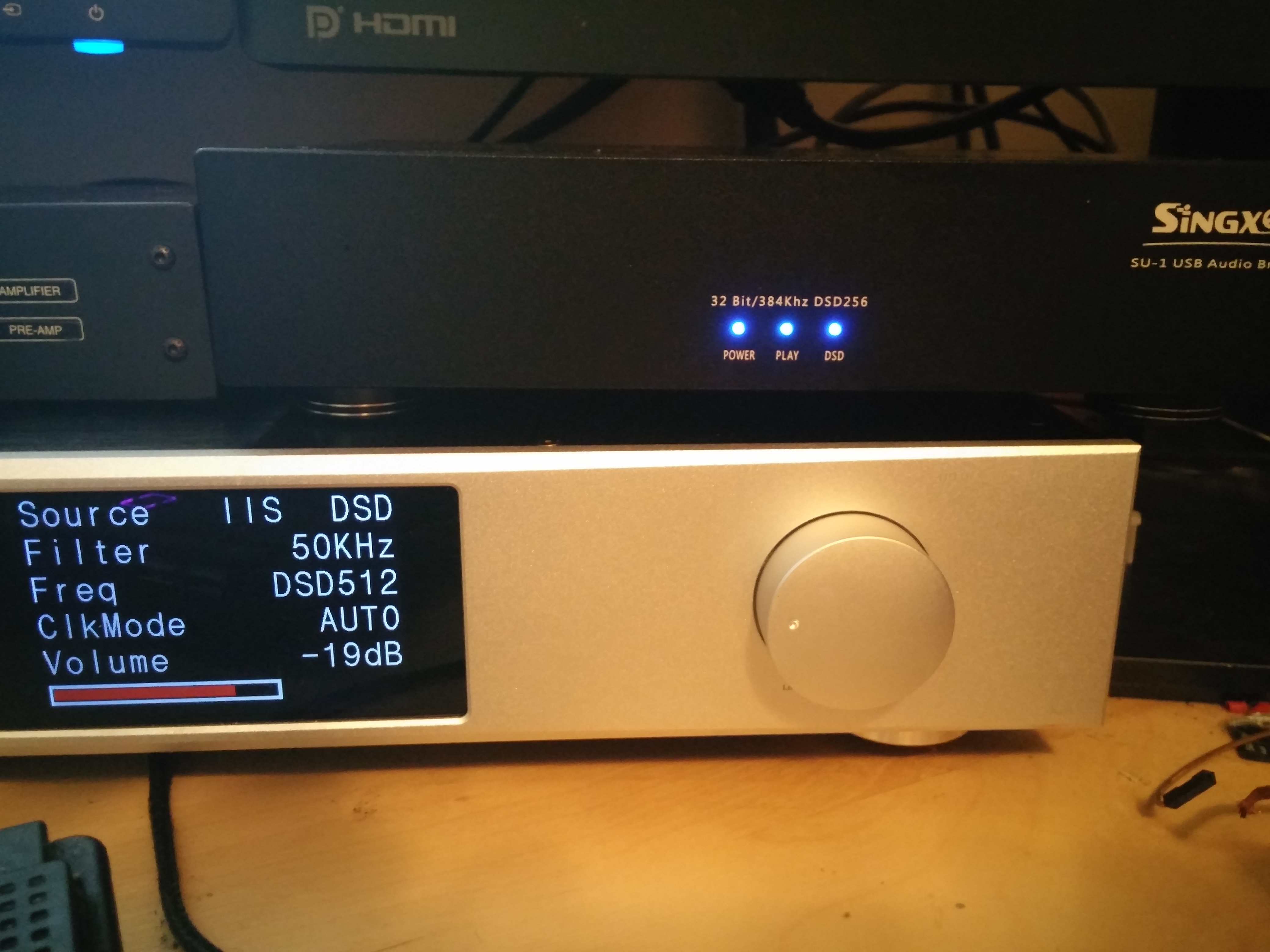
If an active source is connected, the display lights up and shows the input's data, however after a couple of seconds the displays goes off.
The little green leds stay on.

Roberto


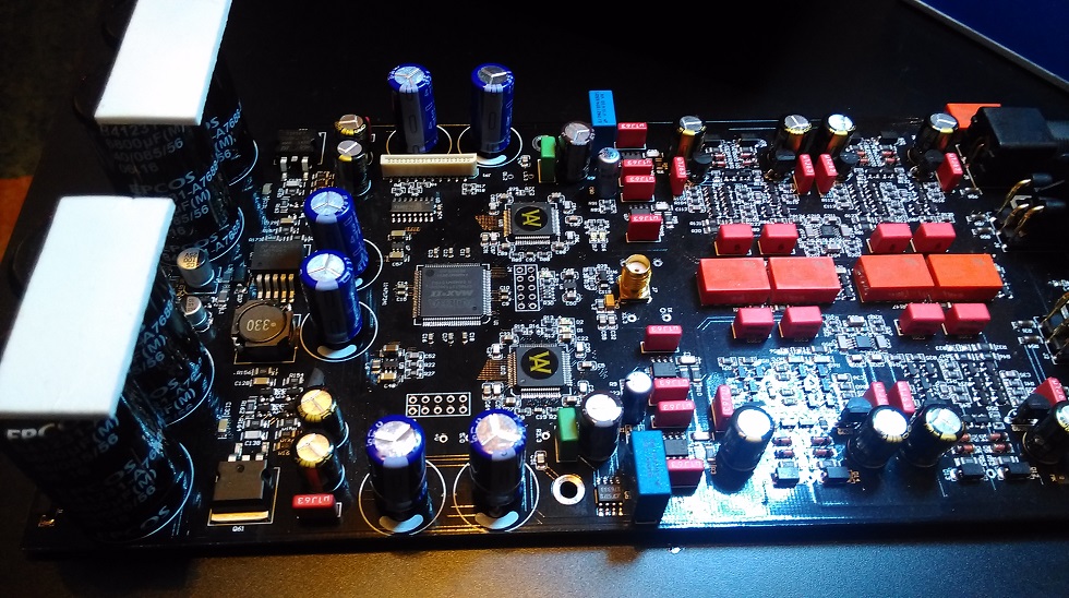
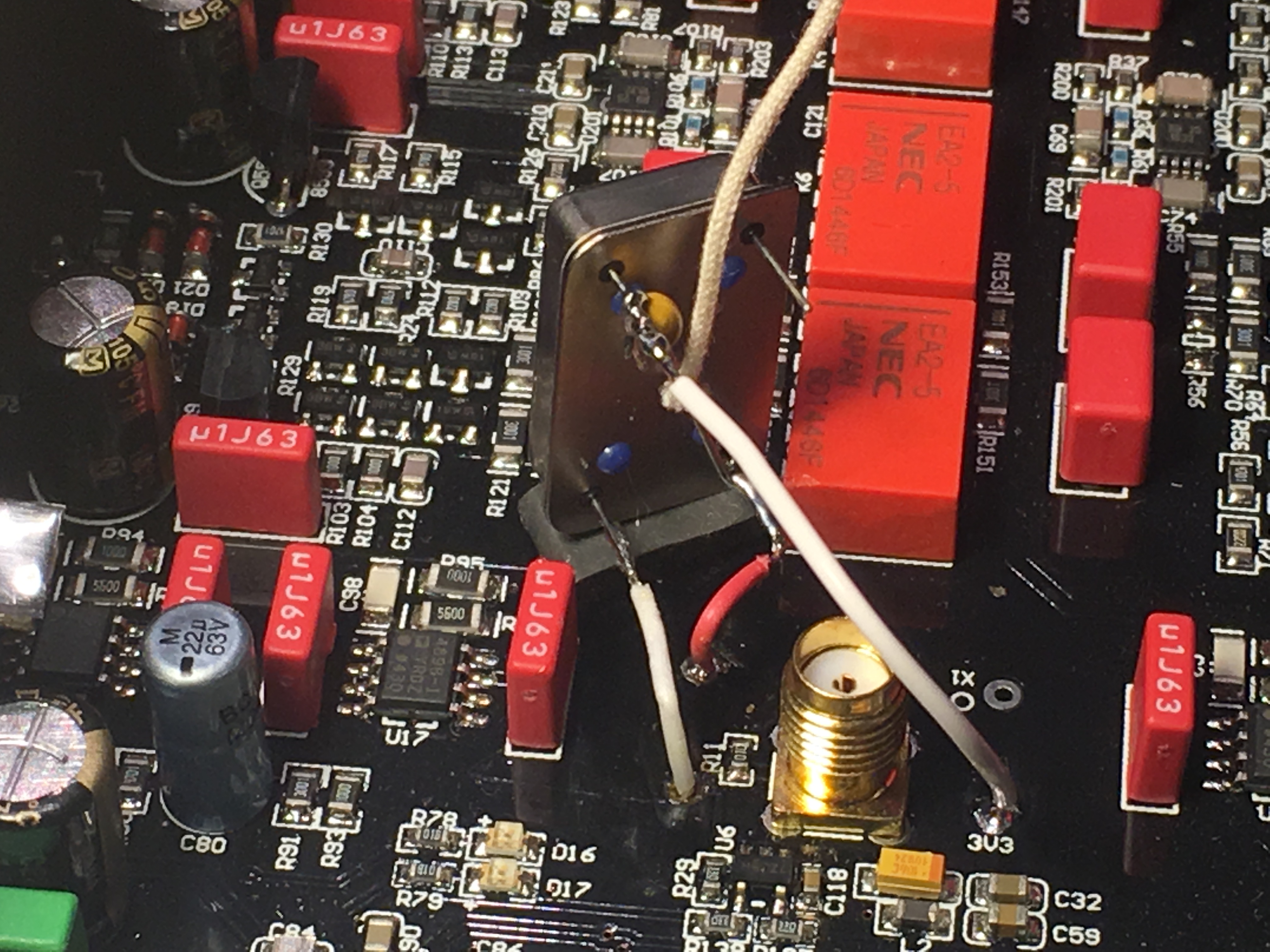
This may be of no help but when I messed up the digital coax connection or had an issue with the ribbon cable the display would light, the LED's on the board would light but a message in the lower right of the LED display would come and go, about the only thing I could read is the word error.  so with that in mind try this if you are comfortable with it.  Remove the top cover of the dac, I will assume your dac is stock (not modded).  Unscrew the coax cable, you may need a small pair of pliers to loosen, mark on end of the cable for orientation.  Do you have a ohm meter?  if so check continuity of this cable signal wire end to end and then shield end to end.  If all good put back on.  Now we will move over to the volume knob area of the inside, there you will see a 3 or 4 wire connector connected to the volume knob board, this wire runs to the LED board.  Very carefully unplug this connector on the volume board and then plug back in making sure it has good contact, then do the same on the LED board be careful as it is kind of tight in there.  (re-reading your post the most likely culprit are the steps below or the LED board is just flat out failing)
 
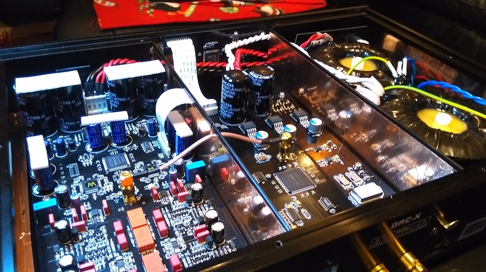
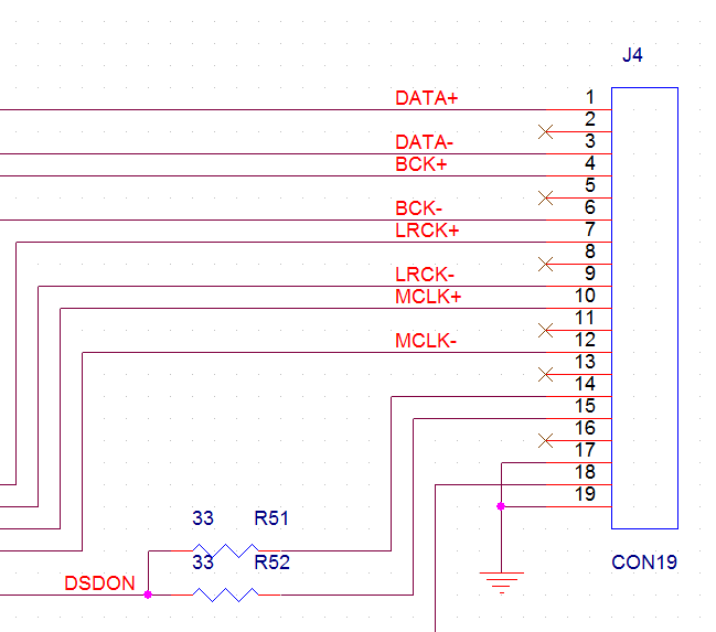
Once these 2 steps are done make sure the USB card is seated all the way down in its slot, just press on it.  Now fire the dac up and see what happens.  If the issue still occurs then unplug and we'll check the white ribbon cables that run from the digital board to the LED board and digital board to output board.  These just pull straight up and out of the socket.  There are 20 wire connectors in that ribbon, under a magnifying glass inspect them (the exposed silver) to make sure none are folded over and not making good clean contact with the socket, if so gently fold the bent one back down, maybe a spot of superglue to secure it back to the ribbon.  Once satisfied all is good put the ribbon cable back the same way it was, the blue plastic at each end is to help gently slide the cable back into the socket.  Do the same with the cable from digital to output board.  Put that back and fire dac up again and hopefully the issue is now resolved and all is good.
 
There also is a tiny brownish ribbon cable running from the LED board to the actual display you can check this (it is on the volume knob side of the board), I cannot remember if it has a socket similar to the white cables or different, visually inspect it for damage.
 
Fingers crossed for good luck.
 
Apr 17, 2017 at 4:46 PM Post #1,173 of 1,320
  Just one more about that capacitor..


I don't think it matters according to Accusilicon.  I used this one https://www.digikey.com/product-detail/en/vishay-bc-components/A104K15X7RF5TAA/1109PHCT-ND/145913.  Before I removed the coax tower I stood the dip14 adaptor up close to the tower  and soldered wires from it to the 3 points on the board and ran this cap between the Vcc and ground pins of the adaptor.  I just thought it would be easier to use a straight wire cap.  Once I removed the coax tower I used the adaptor I linked before as the cap is part of it.
 
Apr 17, 2017 at 5:07 PM Post #1,174 of 1,320
This may be of no help

Fingers crossed for good luck.


Hi, apparently the Kidult guys knew of these things as they asked me to try (most of) what you suggested. I only had a puff of smoke from the DAC board - actually a second one, I think I smelled one when it stopped. I sent it to Hong Kong and they should pick it up soon and reclaim to Gustard...


Roberto
 
Apr 17, 2017 at 5:12 PM Post #1,175 of 1,320
   
I don't think it matters according to Accusilicon.  I used this one https://www.digikey.com/product-detail/en/vishay-bc-components/A104K15X7RF5TAA/1109PHCT-ND/145913.  Before I removed the coax tower I stood the dip14 adaptor up close to the tower  and soldered wires from it to the 3 points on the board and ran this cap between the Vcc and ground pins of the adaptor.  I just thought it would be easier to use a straight wire cap.  Once I removed the coax tower I used the adaptor I linked before as the cap is part of it.

I think I still can solder on the back side of the pcb, straight to adapter pins. There is a lot of space.
I ordered this adapter http://www.mouser.ie/Search/ProductDetail.aspx?R=1107741virtualkey53500000virtualkey535-1107741
 
Thanks Quadman!
 
Apr 17, 2017 at 5:20 PM Post #1,176 of 1,320
  I think I still can solder on the back side of the pcb, straight to adapter pins. There is a lot of space.
I ordered this adapter http://www.mouser.ie/Search/ProductDetail.aspx?R=1107741virtualkey53500000virtualkey535-1107741
 
Thanks Quadman!


That adaptor is perfect.  I chose the one with the cap built in because from the regulator I soldered the 3.3 V positive to the bottom of the board and the ground also to the bottom of the board (at the adaptor pins).  Adding a cap there certainly could also have been done, but I took the easy way out and picked the one with the cap already installed.
 
Apr 17, 2017 at 5:28 PM Post #1,177 of 1,320
Hi, apparently the Kidult guys knew of these things 

Roberto

Bummer, puff of smoke ouch.  thinking back to all the things I did to these boards (not to mention what Simon did, he actually pulled his USB PCI slot out of the board) and everything worked out just fine for me and Simon.  I thought this dac was virtually bomb proof, but components do fail as obviously what happened to yours.
 
Good luck
 
Apr 20, 2017 at 12:46 PM Post #1,178 of 1,320
 
That adaptor is perfect.  I chose the one with the cap built in because from the regulator I soldered the 3.3 V positive to the bottom of the board and the ground also to the bottom of the board (at the adaptor pins).  Adding a cap there certainly could also have been done, but I took the easy way out and picked the one with the cap already installed.

How do you soldiered clock to adapter? Using short wires?
 
I've seen SMD to DIP14 adapter from Accutek (AK14D300-XTAL-04SOJ 4 PIN SOJ CRYSTAL TO 4 PIN (14 PIN FULL SIZE) DIP) but couldn't get to buy anywhere.

 
Apr 20, 2017 at 1:43 PM Post #1,179 of 1,320
  How do you soldiered clock to adapter? Using short wires?
 
I've seen SMD to DIP14 adapter from Accutek (AK14D300-XTAL-04SOJ 4 PIN SOJ CRYSTAL TO 4 PIN (14 PIN FULL SIZE) DIP) but couldn't get to buy anywhere.


I cheated and used clocks in the DIP 14 format, accusilicon (which is what gustard uses) and abracon, both come in dip14 configurations.  But I think this might work for you, double check with the supplier, b0bb pointed to it on the LKS 003 thread around p12 maybe.  http://www.twistedpearaudio.com/digital/cronus.aspx  scroll down botton right to the rhea board ($8.50 us).  
 
Simon just stood his 950 up near the coax tower (signal and ground side) and used very short wires to go from clock to ground and signal he used a twisted pear regulator (trident shunt 3.3v) board between the 5V gustard line and the Vcc of the clock.  This board is only good for .1A so it will not work with the abracon, the Akko I mentioned earlier will work with the Abracon.
 
Apr 22, 2017 at 1:40 AM Post #1,180 of 1,320
Hello,
 
i am a happy user of the Gustard X20 U too.
I did the simply mods on te power (bolts out and twisting the wires enz)
That give a very good result.
On this forum i can read that a external audio interface (gustard u 12) sound better with I2S then the internal usb card in the X20
Can anybody explain me why that gives a better result?
Thank yoy very much and sorry for my bad english.
 
Greetings Ton (netherlands)
 
Apr 22, 2017 at 5:41 AM Post #1,181 of 1,320
External USB bridges has better oscillators (clocks) for XMOS (or Amanero) chip. There is also better quality power supply and then galvanic isolation on top of that.
 
And definitely recommend Singxer SU-1 instead of U12
 
Apr 22, 2017 at 8:25 AM Post #1,183 of 1,320
No need to do anything special just set small DIP switches on the bottom side of the SU-1
 
 
Recommended set up for Gustard DAC is on shenzenaudio www.
It works perfect with Gustard.
 
Apr 23, 2017 at 10:43 AM Post #1,184 of 1,320
Hello Rafabro,
 
thank you for advise.
I am using now a IFI Nano IUSB 3.0 between my pc and Gustard.
When i bring in a Singxer can i use the IFI to?
May the IFI and the U12 is a good combi?
Or maybe sell the IFI and use the money for the more expensive Singxer :)
 
Gr. Ton
 

Users who are viewing this thread

Back
Top