


Walderstorn
500+ Head-Fier
- Joined
- Mar 25, 2015
- Posts
- 754
- Likes
- 126
Thanks Alex, i will try that with some wire from power cord and just cut off the black wire and the shielded (still have to see which was is this) and try to do it.
Thanks Alex, i will try that with some wire from power cord and just cut off the black wire and the shielded (still have to see which was is this) and try to do it.
Thanks a lot. It's works. I am using Oyaide NEO d+ Class S usb cable with isolated ground, Vcc and shield by...insulating tape!Big sound improvement, much cleaner.@
@pakultra thank you very much but turned out to be much more complex than i thought it would be, definitely not something im confortable trying. I guess my friend (the owner of the u12) is screwed and he's probably going to sell it, since he finds it (and so do i) awful that they could've ignored this issue when manufacturing, seems like a huge oversight and i dont think a firmware update will be able to fix it.
Findings on U12 cap values:
I replaced my two 2200uf ultra-low impedance (14 mohm) Nichicon caps with two 5600uf ultra-low ESR panasonic FC caps for experiment. To my surprise, the breathtaking imaging is gone. Everything is a little laid back. To make sure I wasn't imagining differences, I put my 2200uf Nichicon back in, the imaging is back. It turns out that the original cap value of 2200uf is pretty optimal.
Some people insist that audio sounds better with smaller caps so that the circuit is powered more of the time directly by transformer instead of by capacitors. That's the reason I didn't increase the cap value when I replaced them. My experiments with 5600uf caps confirmed this.
Hi pakultra, the downside on modifying audio equipment is that you have to let the replaced components BURN-IN, so, put those Pana's back in and let it them burn-in for at least 100 hours!
You will be surprised what they finally bring you!
Cheers
Alex
@Walderstorn,
D+ and D- two wire data only connection is working now. No positive, no ground in usb wire, data wire shielding connected at U12 only and disconnected from PC.
Here is how I did it:
:
Warning: Do Not use regular usb cable after these mods. You might damage your U12 or PC if you use regular four wire usb cables. Absolutely no USB Positive connection at any time!
Regarding Step 3), please note that we hope Gustard will issue a firmware revision to disable XMOS's Vcc detection function. Once that is done, there will be no need for Step 3. Step 3 connects U12 + 5 with USB Vcc, which is BAD and Dangerous! Take cautions here.
No wiring on the upper side of the pcb:
I replaced the spdif transformer and 2200 uf caps. There are no hookup wires on this side. U12 still look nice and clean.
Nice job pakultra, I didn't took time to measure all of the pins to find groundpin, AES transformer pin 1 is a good find, will remove wire on top and modify to this pin, look cleaner indeed.
About relay bypassing, It's a nice find, but I'm not very fond of this mod because of accidental connecting standard usb cable will destroy U12 or usb-port from pc.
I tried feeding relay with batterypower, there's no sq improvement in comparrison with feeding relay with usb power, at least, with my usb cable.
Cheers
Alex
Step 2) alone is not dangerous. Regular usb cable will not do any damage at this point. You can still hear relay clicking on with usb power connected and off when disconnected.
But Step 2) is pointless without going further for Step 3), which is dangerous.
But we can do a Step 4) to make U12 totally safe with regular USB cables again. I didn't mention Step 4) because so far all steps can be easily reversed and I can return U12 to its original factory condition simply by removing the three connections in steps 1- 3. Step 4 will be a little beyond the point of return.
This is what we need to do for Step 4): remove USB socket Vcc connection to the PCB.
It can be achieved by simply pulling out the USB positive leg in the socket or by cutting the USB Vcc pinout before it connects to pcb. We will need a hot air rework station or Chipquik pack for desoldering the USB socket so that we can cut the Vcc and negative pinout before we put the socket back in. I don't have a hot air station or a Chipquik pack so I can't do it now.
Cheers
pakultra
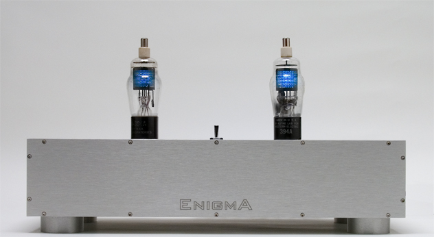
Hi ! what about this USD isolator between the pc and the Gustard ?
http://www.ebay.com/itm/111648127278
I bought one to try out.
It has a power plug receptacle marked 6V-24V.
Any decent PS would be better than the dirty pc usb lines i guess.
What you think ?
Thanks, gino
@Alex thank you for your advice. I will put bigger values back in and let them burn in. I was aware of this burn-in effect but I was just too impatient to wait for a whole week before U12 could sound good again. The effect of replacing original caps with 2200uf Nichicon 14 mohm was instant and immediate. Without a single minute of burn-in, I heard breathtaking imaging. I was expecting the same level of performance from the Pana's... I will order some 4700 uf Nichicon 11 mohm to see if there is a difference between the Nichicon and Pana's.
Cheers
pakultra
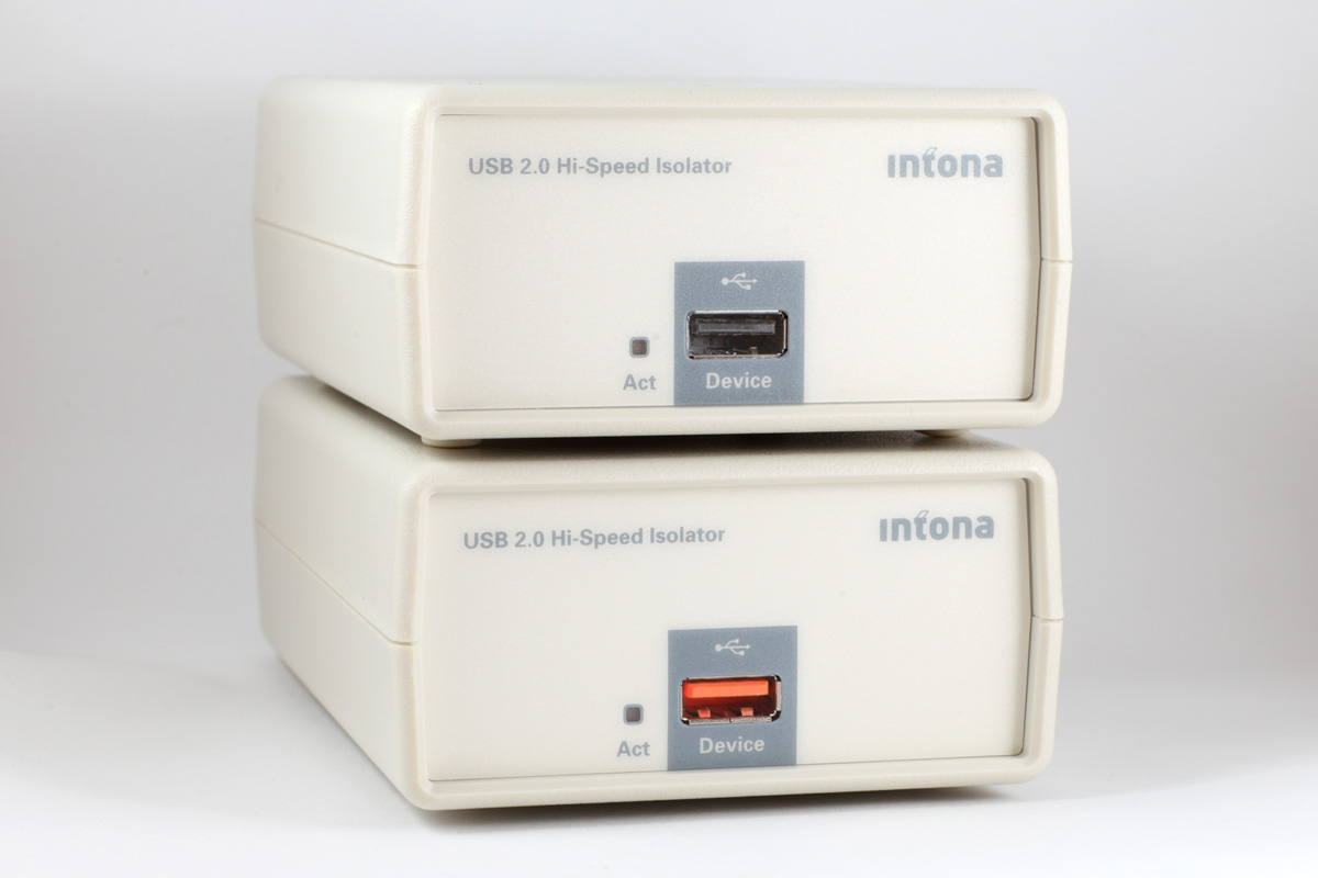
From the Ebay description : "This module is designed based on ADUM4160, a Full/Low speed 5kV USB isolator."
This is USB marketing speak for the low speed stuff so it will not work with 480Mbps USB2.0, if this isolator is used the interface is limited to USB1.1 which limits the audio to a max sample rate of 96kHz.
@Alex thank you for your advice. I will put bigger values back in and let them burn in. I was aware of this burn-in effect but I was just too impatient to wait for a whole week before U12 could sound good again. The effect of replacing original caps with 2200uf Nichicon 14 mohm was instant and immediate. Without a single minute of burn-in, I heard breathtaking imaging. I was expecting the same level of performance from the Pana's... I will order some 4700 uf Nichicon 11 mohm to see if there is a difference between the Nichicon and Pana's.
Cheers
pakultra
The Panasonic FCs are an old design and quite laid back. They were quite popular in taming the sound of the delta-sigma DACs in CD Players 10-15 years ago.
The present day equivalent to the low impedance Nichicons are the Panasonic FMs. The Panasonic FRs are even lower impedance. They are the equivalents of the Nichicon HE and HW respectively.
Agree with abartels, on digital stuff, new caps in my mods take 24-48 hours of continuous operation to settle down.
