GUSTARD DAC-R26 Balanced Decoder R2R+1Bit Dual Native Decoding Music Bridge
Sep 16, 2023 at 11:53 AM Post #7,426 of 8,833
don't understand the fuse requirment, power consumption is <30 W which means 0.125 amps at 240 V.
The fuse specified is a slow blow 3.15 A which is 25 x the normal current.
The fuse is a slow blow one which means it could take more than 3.15A for a short period, so anything delicate will be fried before the fuse blows.
Why isn't the fuse specified as the 630mA one ?
Understand the toroids can draw a higher current on start up, each one is 50 VA at 115V, so 100 VA at 240V is 0.41 A, still well below the 3.15 A fuse specified.
It's true. For 240V, 2x lower current value is required. And 3.14 A is too much even for 120V. Allegedly, the manufacturer installs 3.14A in all devices. It's easier for them that way. The consolation is that the fuse can rarely save the device anyway.
 
Sep 16, 2023 at 11:57 AM Post #7,427 of 8,833
It's true. For 240V, 2x lower current value is required. And 3.14 A is too much even for 120V. Allegedly, the manufacturer installs 3.14A in all devices. It's easier for them that way. The consolation is that the fuse can rarely save the device anyway.
Ah, thanks, so might as well take the fuse out of the circuit and switch the system off if there's a threat of power surges like lightning etc
 
Sep 16, 2023 at 12:07 PM Post #7,428 of 8,833
Further to my experimenting with the transformers I've good news and bad news.
bad news is that the transformers are located too close to each other and it's affecting the sound, boosting some frequencies and just making it sound like detailed noise.
good news is that separating the transformers by 10cm outside of the case produces a much cleaner more coherent musical sound
found this out by moving the transformers towards each other outside the case, so this benefit is on top of removal of any interference the transformers were having on the rest of the circuit.
 
Sep 16, 2023 at 12:10 PM Post #7,429 of 8,833
Why isn't the fuse specified as the 630mA one ?
Understand the toroids can draw a higher current on start up, each one is 50 VA at 115V, so 100 VA at 240V is 0.41 A, still well below the 3.15 A fuse specified.
Because smaler fuse can be blown during powering on. There is a large battery of capacitors that take temporary current many times exceeding continuous power of the transformer rating. Slow blown fuse is used, but it is not enough. Termistor Varistors [edit] can be used to limit in-rush current, like it was practiced in tube TV's, but it affects radiating noise from the rectifier.

You need to trust designers, they know that when temperature increases, fuse will burn at a reduced current. Other manufacturers (like Audio GD) place fuses inside the transformer, a place a temperature raises faster in case of catastrofic failure. Fuse is soldered, an additional benefit, as you don't need to purchase audiophile fuses that hasn't been tested is this particular equipment.
 
Last edited:
Sep 16, 2023 at 1:01 PM Post #7,430 of 8,833

What is transformer inrush current?​

The transformer inrush current is the instantaneous current drawn by the primary winding of the transformer when the transformer is energized with the secondary side left open-circuited. The secondary side of a transformer is energized only by the magnetic flux from the primary side. Therefore there is no current flow in the secondary windings (hence open-circuited for a very short while) at the moment the transformer’s primary winding is energized.

The inrush current does not create any permanent fault in the transformer. Still, it causes an unwanted switching in the circuit breaker (an electrical switch designed to protect an electrical circuit from damage caused by a short circuit or overcurrent).

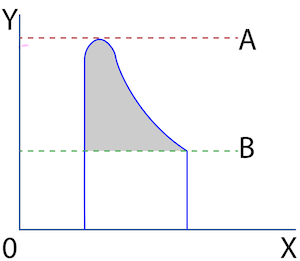
During the inrush current, the maximum value attained by the magnetic flux is over twice the normal flux. The magnitude of inrush current (Figure 2 labeled A) is 2-10 times that of the transformer full load current (Figure 2 labeled B). Toroidal transformers that use less copper for the same power handling can have up to 60 times the inrush to running current.

Transformer peak current (A) and steady-state current (B)
 
Last edited:
Sep 16, 2023 at 1:05 PM Post #7,432 of 8,833

Što je udarna struja transformatora?​

Ulazna struja transformatora je trenutna struja koju povlači primarni namot transformatora kada je transformator pod naponom dok je sekundarna strana ostala otvorena. Sekundarnu stranu transformatora napaja samo magnetski tok s primarne strane. Stoga nema strujnog toka u sekundarnim namotima (dakle otvoreni strujni krug vrlo kratko vrijeme) u trenutku kada je primarni namot transformatora pod naponom.

Ulazna struja ne stvara nikakav trajni kvar u transformatoru. Ipak, uzrokuje neželjeno prebacivanje u prekidaču strujnog kruga (električni prekidač dizajniran za zaštitu električnog kruga od oštećenja uzrokovanog kratkim spojem ili prekomjernom strujom).

Tijekom udarne struje, najveća vrijednost koju postiže magnetski tok dvostruko je veća od normalnog toka. Veličina ulazne struje (Slika 2 označena A) je 2-10 puta veća od struje punog opterećenja transformatora (Slika 2 označena B). Toroidalni transformatori koji koriste manje bakra za isto rukovanje snagom mogu imati do 60 puta veći udar u radnu struju.

What is transformer inrush current?​

The transformer inrush current is the instantaneous current drawn by the primary winding of the transformer when the transformer is energized with the secondary side left open-circuited. The secondary side of a transformer is energized only by the magnetic flux from the primary side. Therefore there is no current flow in the secondary windings (hence open-circuited for a very short while) at the moment the transformer’s primary winding is energized.

The inrush current does not create any permanent fault in the transformer. Still, it causes an unwanted switching in the circuit breaker (an electrical switch designed to protect an electrical circuit from damage caused by a short circuit or overcurrent).

During the inrush current, the maximum value attained by the magnetic flux is over twice the normal flux. The magnitude of inrush current (Figure 2 labeled A) is 2-10 times that of the transformer full load current (Figure 2 labeled B). Toroidal transformers that use less copper for the same power handling can have up to 60 times the inrush to running current.

Transformer peak current (A) and steady-state current (B)
That is why slow fuses are used.
 
Sep 16, 2023 at 2:03 PM Post #7,433 of 8,833
Because smaler fuse can be blown during powering on. There is a large battery of capacitors that take temporary current many times exceeding continuous power of the transformer rating. Slow blown fuse is used, but it is not enough. Varistors could be used to limit in-rush current, like it was practiced in tube TV's, but it affects radiating noise from the rectifier.

You need to trust designers, they know that when temperature increases, fuse will burn at a reduced current. Other manufacturers (like Audio GD) place fuses inside the transformer, a place a temperature raises faster in case of catastrofic failure. Fuse is soldered, an additional benefit, as you don't need to purchase audiophile fuses that hasn't been tested is this particular equipment.
my 3.15A slowblow fuse is protected by the 3A fuse on the mains plug, wouldn't want to buy an expensive fuse and risk it blowing
 
Sep 16, 2023 at 2:26 PM Post #7,435 of 8,833
that is why slow blow fuses are used, but also means their effectiveness at protecting the electronics is lost, there should be a fuse for the electronics and the mains plug fuse can protect the transformers
If you are going to use a fast fuse, you need a much higher value, precisely because the transformer and capacitors, when switched on, draw a much higher current. It lasts a short time so the slow fuse survives.
 
Sep 16, 2023 at 2:46 PM Post #7,437 of 8,833
You guys are thinking too much about nothing.✌️✌️✌️✌️✌️✌️
If Gustard installs a 2.5a as standard and also releases 3.15a, then there is a reason for this and it has also been tested.

They wrote to me that a 2.5 is for normal listeners and 3.15 for audiophiles.
So your concerns and doubts are actually clarified.

The next point is that many manufacturers deliberately build in a fuse with a somewhat lower value, also for cost reasons.
And do not go to the normal power where it would actually be optimal.
Most devices can actually handle more, even if the fuse would blow.
Of course, if you don't overdo it and go from 2.0 to 5.0 a.
If you have a 2.5 a left over even though a 2.0 was installed, nothing usually happens.
Of course, it is also advisable to ask the manufacturer beforehand to be on the safe side, but they usually approve it, because 0.5 a more hardly affects the overall electronics.

Everything that was discussed on the last page about transformers is a theoretically determined value and nothing more.
It refers mainly to the transformer itself.
And not to other factors, such as additional components that also need to be supplied with power.
Bluetooth, Lan, display, etc. also need power and must be taken into account.

If I were to worry about this and the theory is correct that the two transformers sound better when the Dac is removed, I would rather think about it.
Whether you can't isolate it in the middle with something or by enclosing the transformers.😉😉😉😉😉
 
Sep 16, 2023 at 2:48 PM Post #7,438 of 8,833
It is why I used term in-rush current in a separate section related to the old TV sets. The inrush current time is extended if there is a large capacitive load on secondary winding. This aspect I covered first. Audio equipment use vastly oversized capacitors for better filtration.
 
Sep 16, 2023 at 2:54 PM Post #7,439 of 8,833
The next point is that many manufacturers deliberately build in a fuse with a somewhat lower value, also for cost reasons.
Not true. There is no cost saving using a fuse of lower rating.
:)
 
Sep 17, 2023 at 8:33 AM Post #7,440 of 8,833
removed the fuse, now protected by the 3A fuse in the mains plug (240V), has removed the thinness in the sound that was annoying me a bit.

soldered the secondary wires to the pins directly, this has made a big improvement in SQ, solidity, depth, detail etc, was surprised as thought it was a bit extreme, but wanted to try it. Modified the white plastic connectors so they would hold the wires in place after I'd finished soldering, there's one on top of the cap in the picture.

No harshness in my system now at all.

tested the screws and transformer bolts with a neodymium magnet and they are slightly magnetic, could pick them up with the magnet. Tried the transformers with the bolt in and out and there seemed to be a harshness present when the bolts were in, so am running with them removed.

Think that's my mods finished, everything is soldered from the mains plug forward into the dac, no fuse, no iec socket, no voltage selector and transformers removed from the case, sounds gorgeous.
 

Attachments

  • 1694949786988.jpg
    1694949786988.jpg
    4.1 MB · Views: 0

Users who are viewing this thread

  • Back
    Top