Gamma-2 (γ2) DAC Thread
Sep 30, 2009 at 1:27 PM Post #721 of 2,154
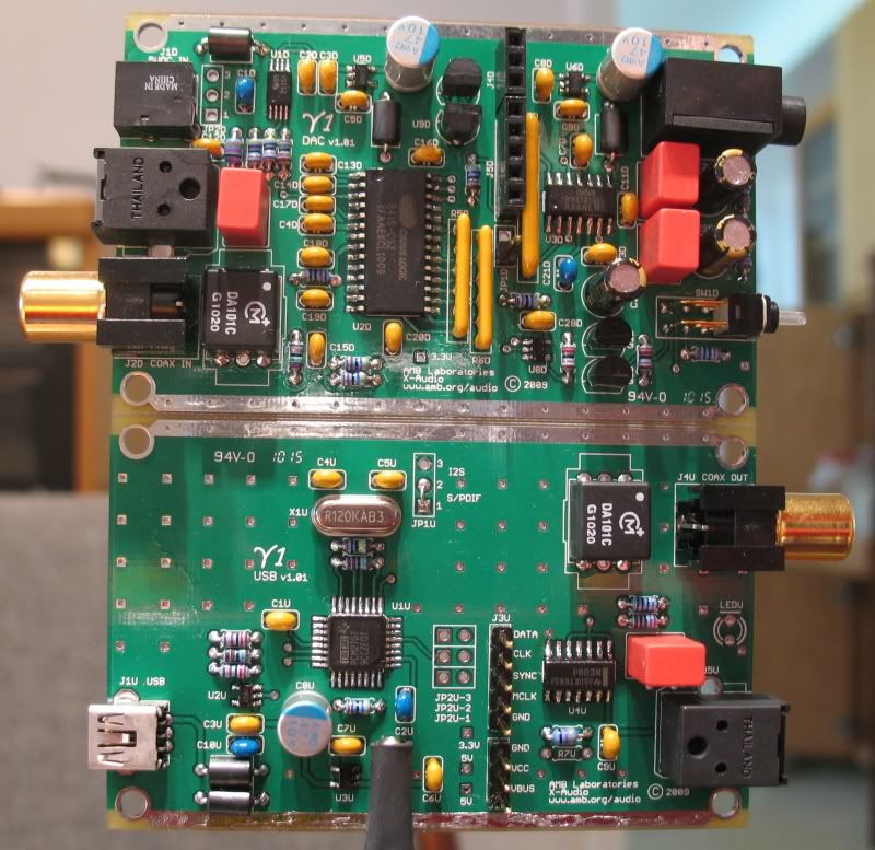
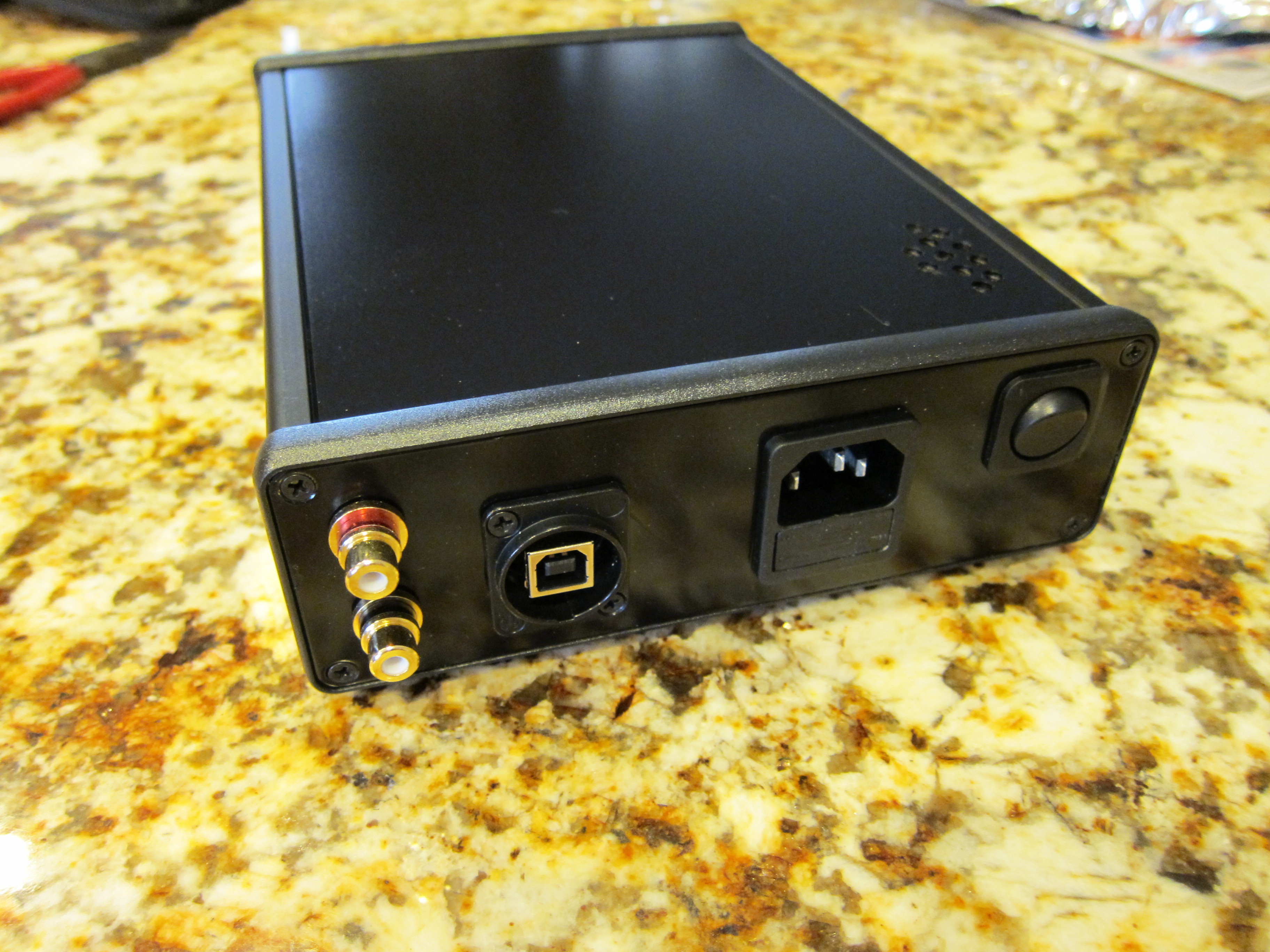
Do any inputs/outputs of the gamma2/mini3 need to be isolated from the chassis like with the ckIII? I wanted to panel mount all the inputs/outputs to make them hold up better. Ive always hated pcb mount connectors, they always seem to get bad joints after a few years.
 
Sep 30, 2009 at 1:42 PM Post #722 of 2,154
Quote:

Originally Posted by dg3f /img/forum/go_quote.gif
i want to build a my own modified desktop version gamma-2 with higher supply voltage and use some other opamp that can be powered with about +-12v as filter and analog output along with diamond buffer so that can drive both low and high impendance headphones


Note that the WM8741 has an absolute maximum voltage input of 4.5V for digital and 7V for analog. You can use LP2985AIM5-5.0CT-ND and LP2985AIM5-3.3CT-ND voltage regulators to regulate 12V down to 5V and 3.3V respectively. The choice of opamp for the y2's output stage will be difficult. But since you say you'll be using a different output stage (maybe IVY or Ballsie or Zapfilter?) then that won't matter.

nightanole, judging from the panels amb sells, everything needs to be isolated.
 
Sep 30, 2009 at 6:35 PM Post #723 of 2,154
Quote:

Originally Posted by ShinyFalcon /img/forum/go_quote.gif
nightanole, judging from the panels amb sells, everything needs to be isolated.


I may be wrong, but the board's ground-plane is connected to signal-output ground so I'm under the impression that isolated outputs are not necessary.
 
Sep 30, 2009 at 6:47 PM Post #725 of 2,154
The S/PDIF coax jack(s) should be isolated so it doesn't defeat the pulse transformer's galvanic isolation. The output jacks should be also be isolated if you're going to be driving headphones, so that the return current from the headphones don't travel through the case.
 
Oct 1, 2009 at 3:13 AM Post #726 of 2,154
Sweet! Got my y2 up and running this evening. Appears tho I have some clipping. Not sure if it's attributed by having to use cheap caps in lieu of the ones in C11/C13. Going to order proper Nichicons tonight along with a zener diode for my mini3 (it blew up when I put the battery in...not sure why but I'll post that in the relevant thread.) Other than the clipping it sounds very good, I'm super psyched that it worked on the first go.
 
Oct 1, 2009 at 4:05 AM Post #727 of 2,154
If you used all the specified parts in the BOM, and the rail voltages are within spec, then you shouldn't encounter any clipping, unless the program material was already clipped in the first place (not unusual these days in the "loudness wars" -- load your ripped songs in a wave editor and prepare to be shocked).
 
Oct 1, 2009 at 4:26 PM Post #728 of 2,154
Quote:

Originally Posted by amb /img/forum/go_quote.gif
The S/PDIF coax jack(s) should be isolated so it doesn't defeat the pulse transformer's galvanic isolation. The output jacks should be also be isolated if you're going to be driving headphones, so that the return current from the headphones don't travel through the case.


the grounds on both the rca's and the 3.5mm out are connected directly to the ground plane, which is connected to the chassis.

If i use panel mount connectors can i just connect the connectors ground to the original rca's ground point, and not isolate them from the chassis? It seems impossible to isolate them from chassis since they connect directly to the ground plane in stock form.

The only ground i see i need to isolate is the usb connector since it goes thru a bead.
 
Oct 1, 2009 at 6:51 PM Post #729 of 2,154
Quote:

Originally Posted by nightanole /img/forum/go_quote.gif
the grounds on both the rca's and the 3.5mm out are connected directly to the ground plane, which is connected to the chassis.

If i use panel mount connectors can i just connect the connectors ground to the original rca's ground point, and not isolate them from the chassis? It seems impossible to isolate them from chassis since they connect directly to the ground plane in stock form.


While they're all connected, if you use un-isolated jacks, then there will be multiple paths of "ground" (through the wiring, and through the case) for ground, which creates mini ground loops. It may or may not matter, but generally it's best to avoid such a scenario.
 
Oct 1, 2009 at 11:32 PM Post #731 of 2,154
good soldering is really all that is needed to assemble these kinds of projects.

no new design work is needed. just soldering, really
wink.gif
 
Oct 1, 2009 at 11:34 PM Post #732 of 2,154
Quote:

Originally Posted by Fuzzy OneThree /img/forum/go_quote.gif
Would this be too ambitious of a project for someone who has only made a few cMoys and a Millet Starving Student?


It is a question of your soldering skills. The layouts are compact but not difficult. There is a fair amount of Surface Mount involved, here is a link to an excellent tutorial. The Bantam Dac has a good tutorial on it as well, I actually prefer the method there, YMMV.
I was surprised by how much I enjoy the SMT work. All it takes is a steady hand, focus and a good magnifier. Not to mention the soldering tools and flux.
 
Oct 2, 2009 at 1:19 AM Post #733 of 2,154
While there is a question on SMT soldering, I do have another novice question on soldering on the ground plane. How to get the solder flow? Do I need a higher power solder or I should heat the area longer? I myself don't think the latter one is a good idea, since the heat will damage the component, and the ground plate may actually dispenses heat faster.
 
Oct 2, 2009 at 3:11 AM Post #734 of 2,154
Quote:

Originally Posted by Fuzzy OneThree /img/forum/go_quote.gif
Would this be too ambitious of a project for someone who has only made a few cMoys and a Millet Starving Student?


I'd imagine you'd be fine. The gamma1/2 were my first soldering projects involving surface mount components and the only part I found semi difficult was the U5 IC because the leg pitch was small and I didn't want to screw it up being a fairly pricey chip.

Once you get the technique down (that tutorial video is very good) it doesn't take too long to propagate the board. Just make sure you have the right equipment (flux pen, fine tip for your iron, magnifier) and watch the polarity on parts that require it.

Overall I think it took me like 6 hours for both pieces. I'm curious as to how long it takes the more experienced builders to build these.
 
Oct 2, 2009 at 4:09 AM Post #735 of 2,154
Quote:

Originally Posted by dumbears /img/forum/go_quote.gif
While there is a question on SMT soldering, I do have another novice question on soldering on the ground plane. How to get the solder flow?


If you have an adjustable temperature soldering station, crank the heat way up to solder the ground pads, a bit of additional liquid flux helps too. This let's you get the pads hot enough to do the job quickly.

Fortunately, most of the pads that have ground plane connections on both sides of the board are passive parts, and those are not easily damaged by heat.
 

Users who are viewing this thread

Back
Top