First cMoy NO SOUND hellllpp!!!
Jun 20, 2008 at 1:45 AM Thread Starter Post #1 of 44

GR/NDER

New Head-Fier
Joined
May 17, 2008
Posts
25
Likes
10
I followed tangents instruction fine until the wiring. Ive spent the last 6 hours trying to figure it out.

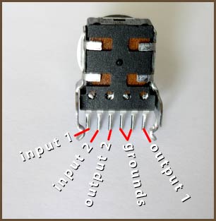
Specifically, on the tutorial diagram hes got a "left" and a right" coming out of the IN jack. which would make me think they go to the "In 1" and "In 2". but no! coming off the protoboard hes also got a "l.in" and a "r.in".

Im so confused.

Heres a pic of what ive got at the moment. No sound but LED lights up. Earlier i had it so on on full volume it would make sound, but it wasnt amplifying anything. also, had a wire crossed or something at one point and the amp got hot enough to burn my finger. what a day...

Im going to go shoot something now.

cmoy1es6.jpg
 
Jun 20, 2008 at 2:03 AM Post #2 of 44
Did you do any testing before you cased it up? Do you have a meter (DMM)?

Go thru the tests for voltage (measure from the virtual ground to V+ on the chip pin 8, and V- on the chip pin 4).

Everything appears to be in the right places physically, and your pot appears to be using the correct pins/pinout. Most no sound problems are signal not getting to the input correctly (jack wiring, pot wiring, etc.), something miswired in the feedback loop (pay particular attention to the "M" jumpers as these are what tie the feedback loop together), or the output jack.
 
Jun 20, 2008 at 2:17 AM Post #3 of 44
If the LED is working, then you have the power section hooked up fine. On my first CMoy, I found the wiring of the volume knob confusing. I looked at your picture and compared it to my build notes and do not see a problem. It appears you have the volume control wired correctly. Also verify the pins on your jacks. They look like Radio Shack models, ones I did not use.
 
Jun 20, 2008 at 2:28 AM Post #4 of 44
Quote:

Originally Posted by Pars /img/forum/go_quote.gif
Did you do any testing before you cased it up? Do you have a meter (DMM)?

Go thru the tests for voltage (measure from the virtual ground to V+ on the chip pin 8, and V- on the chip pin 4).

Everything appears to be in the right places physically, and your pot appears to be using the correct pins/pinout. Most no sound problems are signal not getting to the input correctly (jack wiring, pot wiring, etc.), something miswired in the feedback loop (pay particular attention to the "M" jumpers as these are what tie the feedback loop together), or the output jack.


Thanks.

They are both getting about the same readings. I measure from the V+ and V- to the ground in the center.

I dont know what you mean by chip pin 8, or 4.

Its funny that you mention the no sound problems and wiring being the problem.. cus thats exactly where i got lost.
 
Jun 20, 2008 at 2:42 AM Post #5 of 44
Quote:

Originally Posted by GR/NDER /img/forum/go_quote.gif
They are both getting about the same readings. I measure from the V+ and V- to the ground in the center.

I dont know what you mean by chip pin 8, or 4.


Someone please correct me if I'm wrong (still working on my first CMoy myself and I have no prior experience with this sort of thing), but as I recall the pin layout on a chip is counted counterclockwise from the dot/indent on the chip. This site has a picture that may be helpful.
 
Jun 20, 2008 at 2:58 AM Post #7 of 44
Thanks for the pics.

I measured from the ground (downthe center) to chip pin 4 & 8 and got the same reading for both.... Anyone notice anything wrong with my wiring?

I got the jacks from Mouser btw.
 
Jun 20, 2008 at 3:25 AM Post #9 of 44
Your input wires from the pot to the board are awfully close to the "M" jumpers and are stripped back enough that there is a good possibility of a short there. I would move them around to the other side of the input film caps.

Probably the next thing I would do would be to pop the opamp out, and with your meter set to ohms mode, ohm out each pin on the opamp socket to ground and verify it against the schematic. For example, pin 3 of the opamp has a 100K resistor to ground. If you don't see 100K when ohming this out, you have a problem. Also, like pins should be approximately the same. 1-7, 2-6, 3-5. With stock resistor values, you should see approximately:

1 and 7: 11k (R5 + R4 + R3)
2 and 6: 1k (R3)
3 and 5: 100K (R2)

If that all checks out, then ohm each adjacent pin to the next looking for shorts.

You could also ohm out the input jack to the board, and verify that the pot is working correctly.
 
Jun 20, 2008 at 4:00 AM Post #10 of 44
What about the L & R points on the input jack? Where on the pot do they connect? The OUTPUT? Even though they go from the input jack to the pot? I dont understand it because on the diagram theres a "l.in" and a "r.in" going from the protoboard to the pot as well. thats 4 in's! how the hell do i know what goes where?

another thing, in his "tight layout" he doesnt use numbers, he uses left/right, but this pic he uses numbers.

annotated-evj.jpg
 
Jun 20, 2008 at 4:22 AM Post #12 of 44
Quote:

Originally Posted by GR/NDER /img/forum/go_quote.gif
What about the L & R points on the input jack? Where on the pot do they connect? The OUTPUT? Even though they go from the input jack to the pot? I dont understand it because on the diagram theres a "l.in" and a "r.in" going from the protoboard to the pot as well. thats 4 in's! how the hell do i know what goes where?

another thing, in his "tight layout" he doesnt use numbers, he uses left/right, but this pic he uses numbers.

annotated-evj.jpg


There used to be a good graphic here (probably from MisterX), but at any rate, the L&R from the input jack connect to the Input1 and Input2 pins on the pot. The output pins on the pot go to the protoboard. Doesn't matter which channel goes where, just don't mix them (i.e. one channel uses input1 and output1). Yours appears to be wired correctly, but you can verify it with your ohmeter. Connect it to the input jack red or blue wire, then connect the other lead to the connection on the protoboard. As you turn the pot up in volume, you should see the resistance decrease from around 10k for a 10k pot to near 0. Measuring from protoboard connection to ground will show the opposite (increase as you turn up volume).
 
Jun 20, 2008 at 7:36 PM Post #14 of 44
Quote:

Originally Posted by ls206 /img/forum/go_quote.gif
Can you post a pic of the underside?


Here you go...

undersidecmoytl0.jpg


I cant find any shorts on top or bottom. I even took the xacto knife in between each soldering point.
 
Jun 20, 2008 at 9:11 PM Post #15 of 44
You need to add solder to many of the connections, particularly those of the op-amp socket. Some of them look like they may not be making contact. Try to fill the entire hole and surround the pin or lead. Make sure you heat both the lead and the pad... you should be able to see the solder "flow" by itself if you are doing it correctly.
 

Users who are viewing this thread

Back
Top