t52
100+ Head-Fier
- Joined
- Jun 12, 2006
- Posts
- 111
- Likes
- 10
Quote:
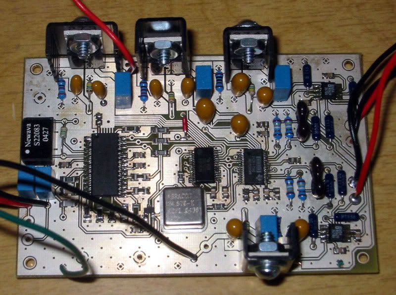
hope so too... chips are pcm1794 and ad1896 (btw. you sent them to me
 )
)
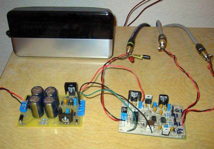
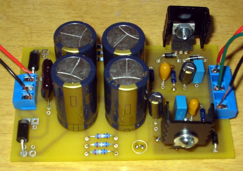
power supply is nonexistant up to now, probably will use the +/-15V lm317 supply i already have for my active crossover for testing...
...and i need a coax spdif source - all my sources only have toslink (optical) outs :/
if i had a tssop/dip adapter i'd breadboard a pcm2902 usb -> spdif converter soon - lots of work ahead...
| Originally Posted by ezkcdude That's great. I'm hoping everything works. What chips are you using, and what is your power supply? |
hope so too... chips are pcm1794 and ad1896 (btw. you sent them to me
power supply is nonexistant up to now, probably will use the +/-15V lm317 supply i already have for my active crossover for testing...
...and i need a coax spdif source - all my sources only have toslink (optical) outs :/
if i had a tssop/dip adapter i'd breadboard a pcm2902 usb -> spdif converter soon - lots of work ahead...