Quote:
Hi,
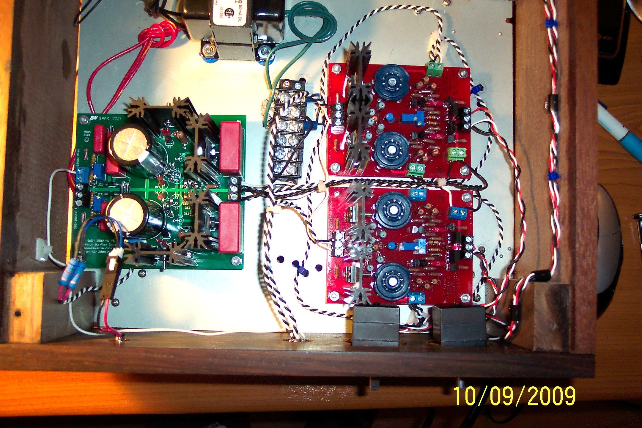
I've assembled the PSU completely using the parts from the BOM. In initial check up, everything measures up correctly to the values that are specified on the Cavalli website. The only issue I have is setting the bias voltage. The bias voltage maxes at around 535V, and it won't go any higher (trimpots are already making clicking noise). Any idea what's wrong?
I'm getting +300V and -300V rails, T1-T2 360mV, T3-T4 410mV, T1 and T3 to ground measures ~330V.
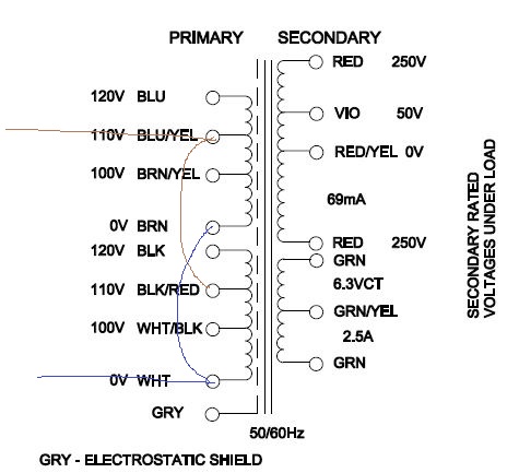
I'm using the 369JX Hammon travo, which is the universal version of the 269JX.
Thanks.
Alex,
can you help me out on this issue? Looking at the schematic of the PSU, the input from the travo is 250-0-250, then after going through the two diodes, is it possible to get the voltage to be higher than 500V on the high bias terminal?
If instead I use a 300-0-300 secondary voltage on the travo (I do that by hooking up the primaries on 200V, instead of 230V), then I didn't have any problem getting up to 600V on the high bias terminal. A friend I talked to recommended changing C5 to the mylar type (I think this is what Al used on his built, looking at the pictures he posted) to help get a higher voltage.


")
