Elekit TU-8200 DX Headphone/Speaker Amp Review
Sep 20, 2015 at 4:58 PM Post #376 of 1,441
See you all at RMAF!

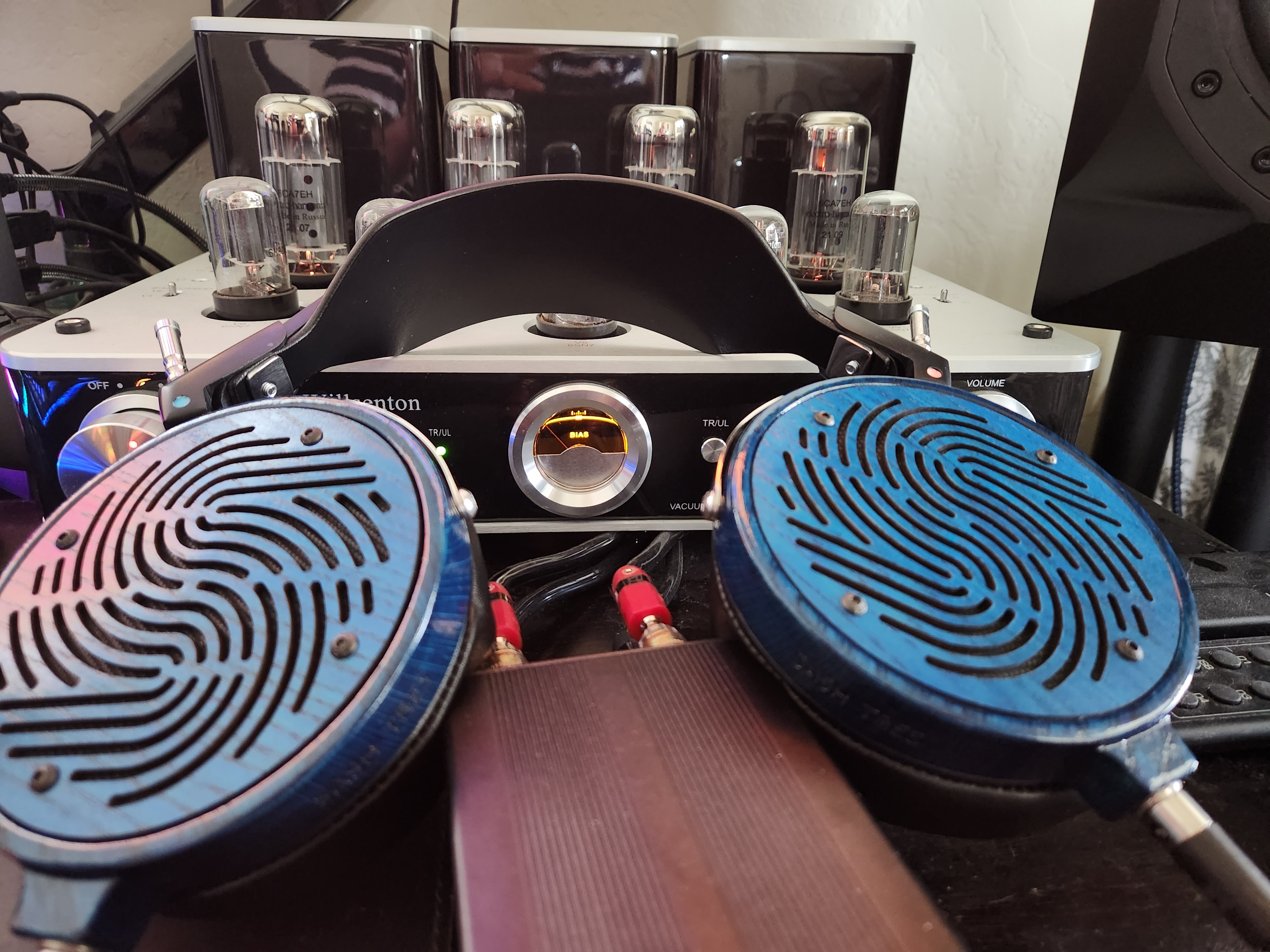
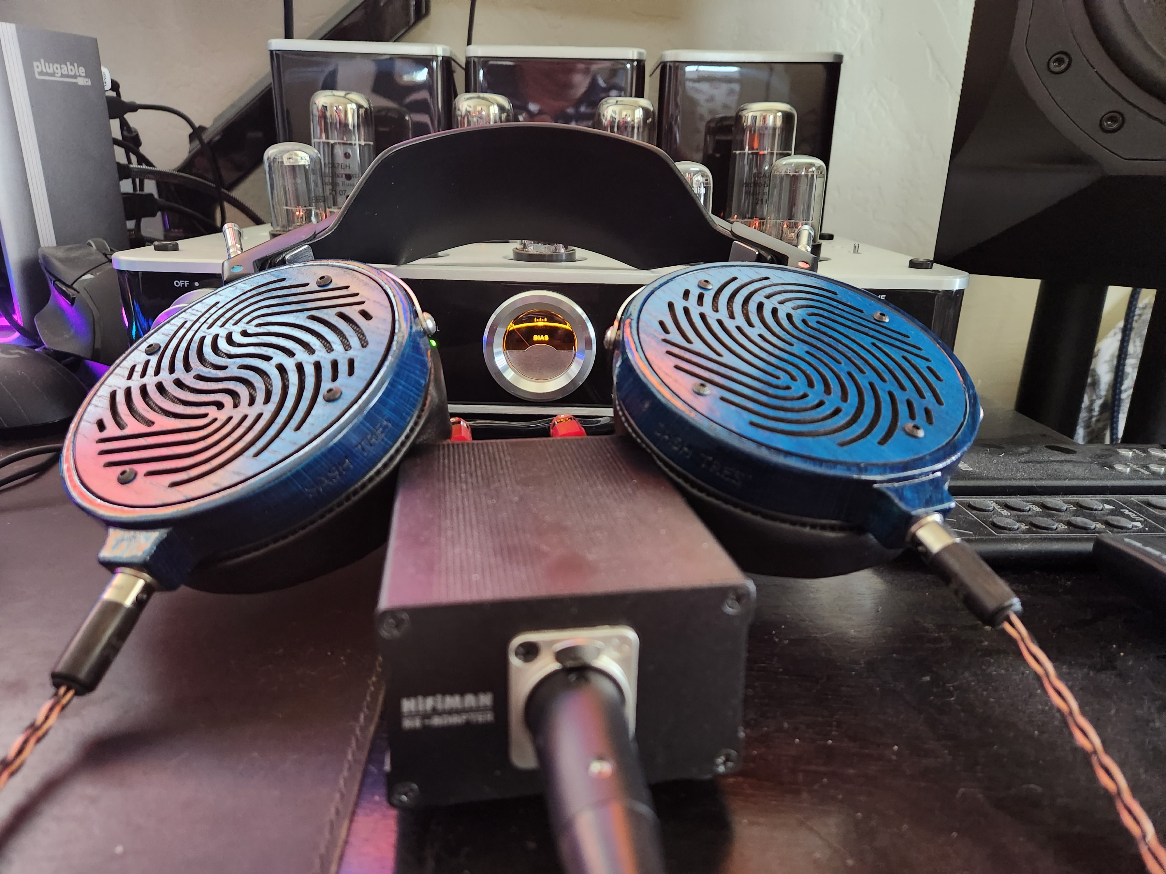
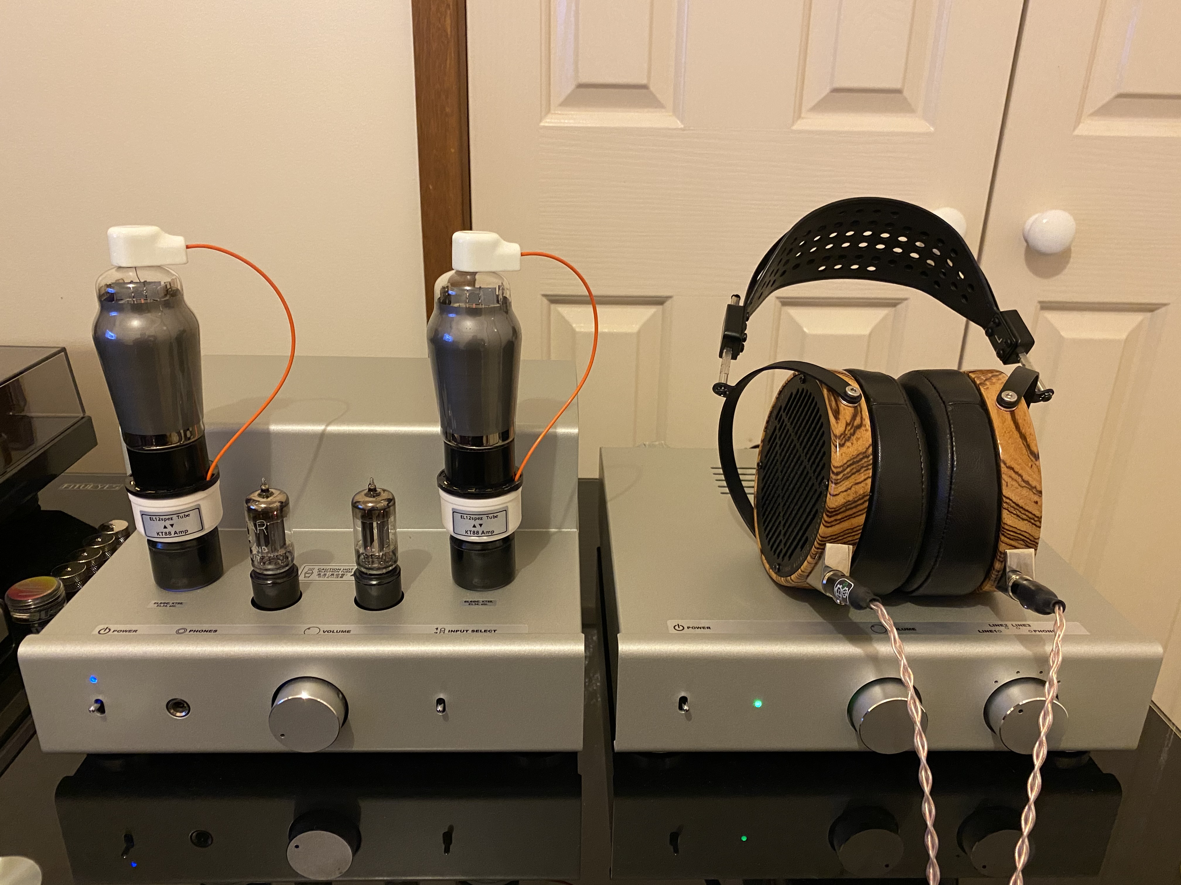
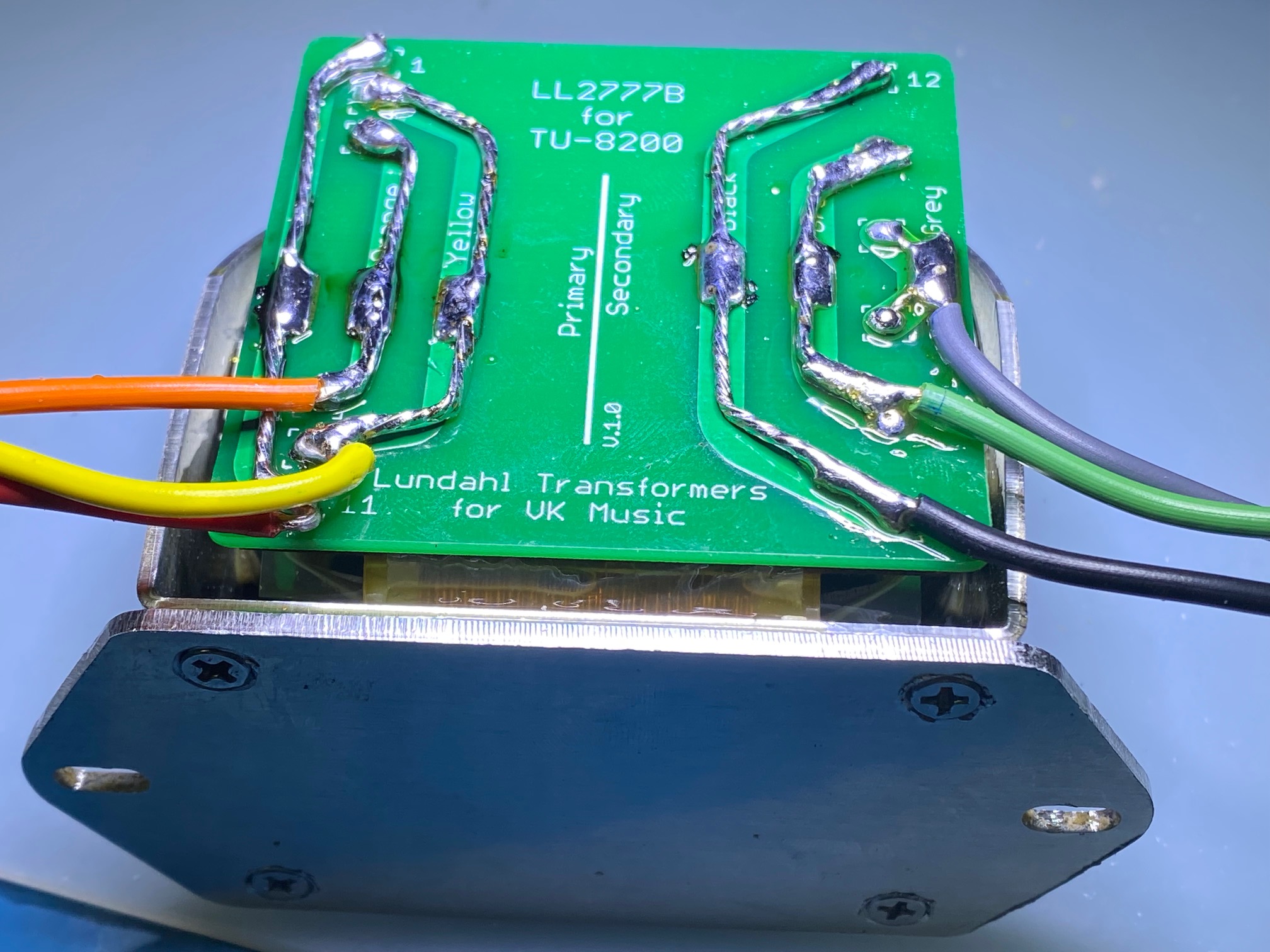
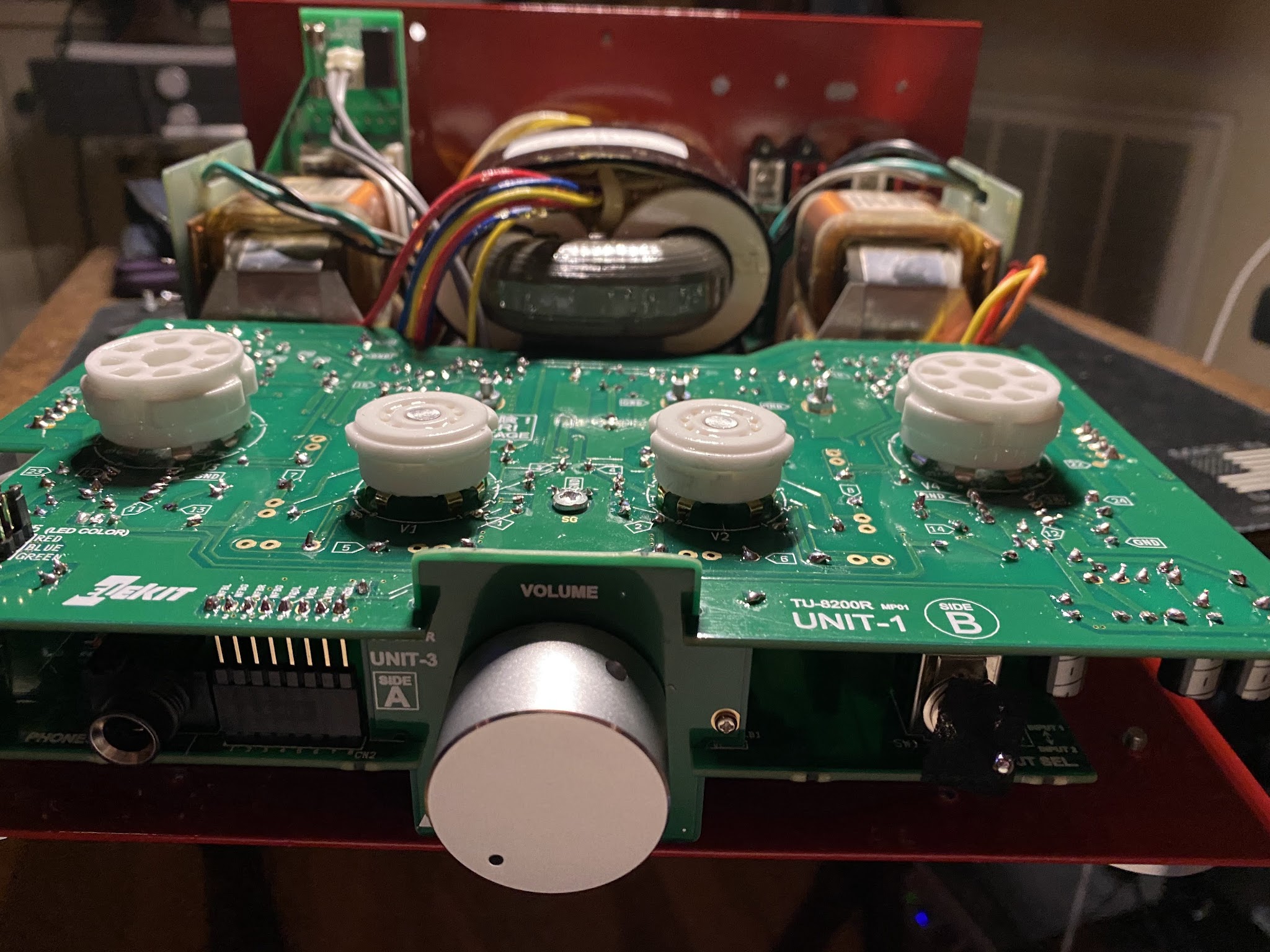
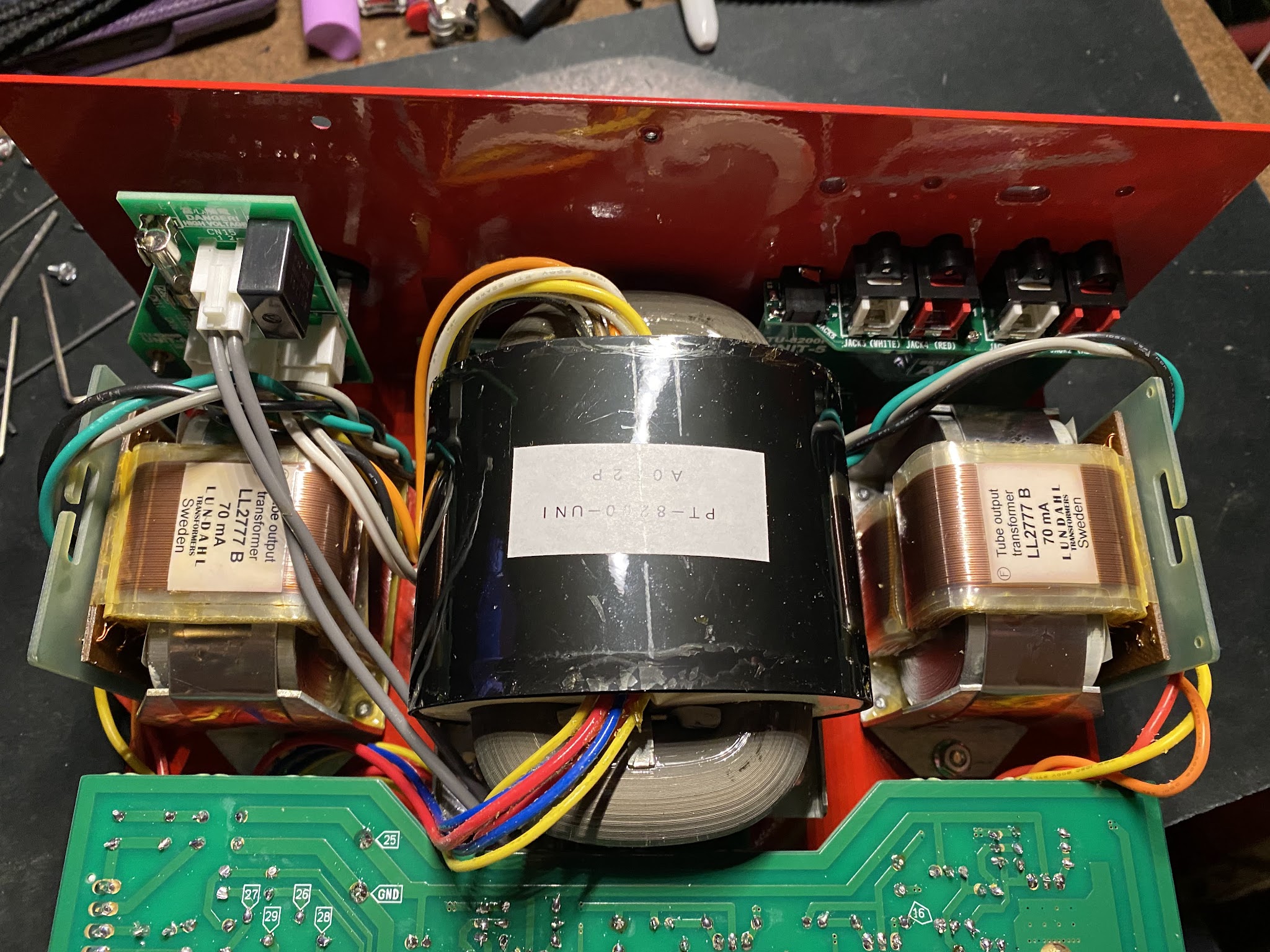
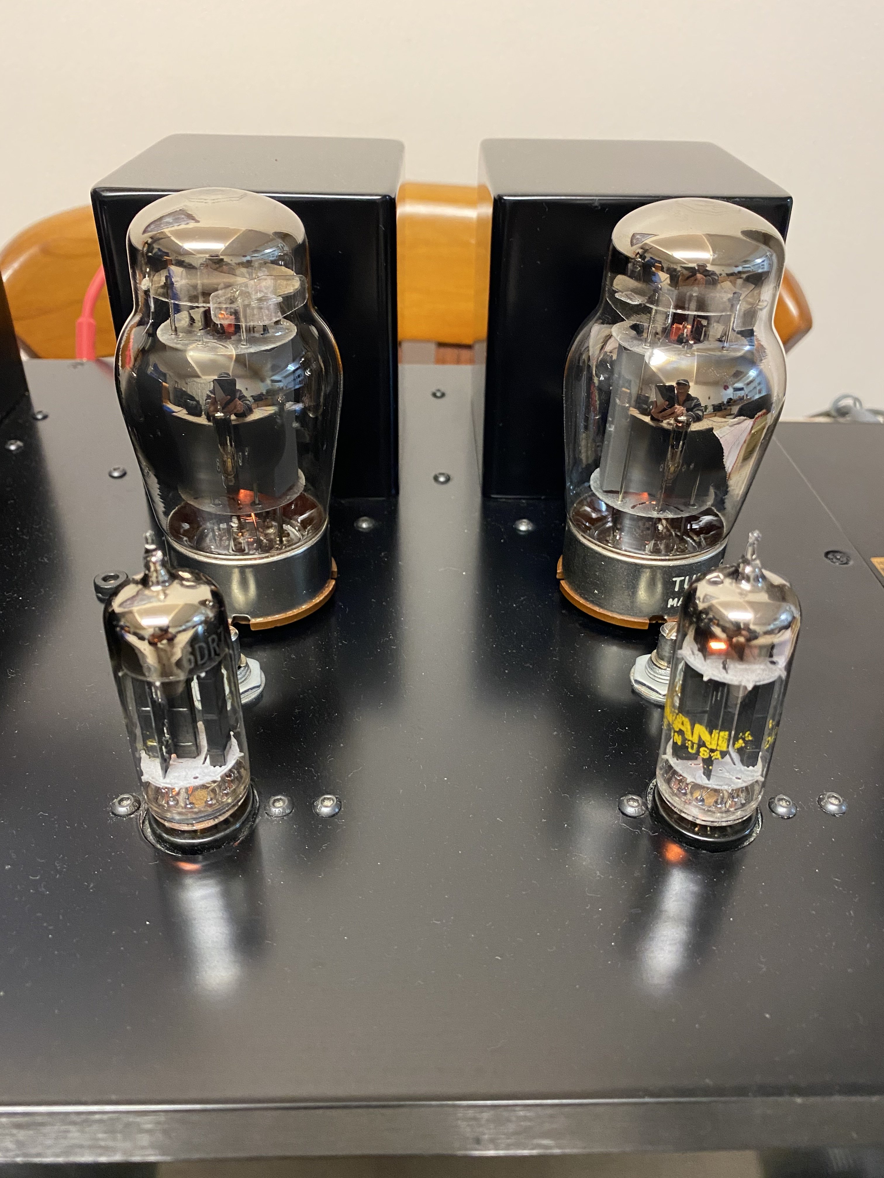
My Elekit is still working, it was just the kt88 that got destroyed. I definitely can't recommend PSVane anymore. Anyway I may pass the 8200 along to fund the purchase of an 8300, as I'm not using headphones (worthy of that level of amping) anymore.
 
Sep 22, 2015 at 9:52 PM Post #378 of 1,441
I'm actually thinking it could have been caused by handling with bare hands? At least thats what Grant Fidelity site says. Either way my Mullard el34 are still going strong.
 
Sep 23, 2015 at 11:47 AM Post #379 of 1,441
I don't think your bare hands would be the culprit...
 
Sep 23, 2015 at 9:35 PM Post #381 of 1,441
That does seem a bit weird, that is if they are stating that this will definitely cause the tubes to fail.
 
I do remember reading a long time ago that oil from your hands can rub off onto the glass of the tube, creating "heat spots", where excess temperature has issues dissipating, but I've never used gloves with any of my tubes and don't believe it has ever caused issues.  I do not own any Psvane tubes though.
 
Was it just the Psvane tubes that they said this causes issues with, or all tubes in general?  It would be very strange if they stated that this was only a problem with Psvane...
 
I hope your luck improves and I'm glad the Mullards are holding up.
 
Sep 24, 2015 at 7:33 PM Post #382 of 1,441

My TU-8200 kit is on the way.
bigsmile_face.gif
Thanks a lot for the great information here.
 
I can’t comment anything about the “great sound” yet but I believe this kit was designed very carefully. How?  The detail assembly drawings/schematics are amazing. This effort in documentation convinces me that Elekit have very good design process, which normally will makes a good design.
 
Sep 24, 2015 at 9:47 PM Post #383 of 1,441
Very cool, congrats on the purchase!  I'm sure you won't be disappointed, it truly is a great amplifier and I agree, design is very important.  The sheer versatility and functionality of this amplifier is a testament to the great design of Elekit.
 
Did you happen to purchase the DX version?
 
I hope the build goes well and let us know how it progresses!
 
beerchug.gif
 
 
Sep 24, 2015 at 10:29 PM Post #384 of 1,441
Thanks Effusion. I feel very sorry I didnt order from victor even after learned so much from here. Major reasons are low austrlian dollar and shipping cost. I once tried HD600 on a tube headphone amp and i coulndt tell the difference, so i set low budget for the first try. Luckily I found amazon in jp also offers this kit, not dx parts. Hopefully you guys will still help me if i have questions.
 
Sep 24, 2015 at 10:43 PM Post #385 of 1,441
Thanks Effusion. I feel very sorry I didnt order from victor even after learned so much from here. Major reasons are low austrlian dollar and shipping cost. I once tried HD600 on a tube headphone amp and i coulndt tell the difference, so i set low budget for the first try. Luckily I found amazon in jp also offers this kit, not dx parts. Hopefully you guys will still help me if i have questions.


Congrats !!!
 
If you have any questions that can't be answered here. Try Elekit directly, they respond quickly in english...
 
Sep 29, 2015 at 11:08 PM Post #386 of 1,441
I didn't quite understand this L shape joint issue when I read this thread, till I got my hands on the kit last night.
 
This is an obvious design defect to me. Solder is soft and kind of fluid under mechanical stress.
 
I bent the cut off component leads into a small L shape and buried them under each solder bulb. Hopefully the flexible wire will take the mechanical stress. This took me lots of time and I haven't here the tube sound  yet.
 
Sep 29, 2015 at 11:57 PM Post #387 of 1,441
  I didn't quite understand this L shape joint issue when I read this thread, till I got my hands on the kit last night.
 
This is an obvious design defect to me. Solder is soft and kind of fluid under mechanical stress.
 
I bent the cut off component leads into a small L shape and buried them under each solder bulb. Hopefully the flexible wire will take the mechanical stress. This took me lots of time and I haven't here the tube sound  yet.


Mine hasn't failed...
 
Sep 30, 2015 at 9:53 AM Post #389 of 1,441
  I didn't quite understand this L shape joint issue when I read this thread, till I got my hands on the kit last night.
 
This is an obvious design defect to me. Solder is soft and kind of fluid under mechanical stress.
 
I bent the cut off component leads into a small L shape and buried them under each solder bulb. Hopefully the flexible wire will take the mechanical stress. This took me lots of time and I haven't here the tube sound  yet.

 
I don't think this is a real design defect that we should worry about because there are several L-shaped solder joints instead of one plus an additional L-shaped metal corner piece attached to both PCB boards with screws for better mechanical rigidity. This is a common electronics PCB technique and I have seen it a lot before. It should be alright in the long run provided the two PCB boards were soldered at a right angle and did not encounter too much stress when installed to the amplifier rear panel. It is important to screw the metal L-shaped piece BEFORE soldering I think. Even a better idea to test the angle first by putting the board against the rear panel and adjust the angle if necessary before soldering. When I was putting mine together, I applied lots of solder to those connections to make sure that they will hold strong afterwards without losing connectivity. No problem so far.
 
There is one possible heads-up moment in this amplifier is that the stack of wires going from the central power transformer to the AC UNIT board (if I remember correctly) can prevent the top cover from installing easily. When putting the top metal cover into place there is a chance that the wires can be crimped between and potentially shortened by the metal cover and the transformer if squeezed hard. Therefore when assembling it is a good idea to use a small wooden thin ruler or a stick and carefully pry the wires from being stuck in between those two metal parts. I learned it later after wondering why the top cover did not align easily with the screws like something prevented it from seating correctly. After figuring out that it was the wires - the problem was solved. Just my .02.
 
Sep 30, 2015 at 7:43 PM Post #390 of 1,441
   
I don't think this is a real design defect that we should worry about because there are several L-shaped solder joints instead of one plus an additional L-shaped metal corner piece attached to both PCB boards with screws for better mechanical rigidity. This is a common electronics PCB technique and I have seen it a lot before. It should be alright in the long run provided the two PCB boards were soldered at a right angle and did not encounter too much stress when installed to the amplifier rear panel. It is important to screw the metal L-shaped piece BEFORE soldering I think. Even a better idea to test the angle first by putting the board against the rear panel and adjust the angle if necessary before soldering. When I was putting mine together, I applied lots of solder to those connections to make sure that they will hold strong afterwards without losing connectivity. No problem so far.
 
There is one possible heads-up moment in this amplifier is that the stack of wires going from the central power transformer to the AC UNIT board (if I remember correctly) can prevent the top cover from installing easily. When putting the top metal cover into place there is a chance that the wires can be crimped between and potentially shortened by the metal cover and the transformer if squeezed hard. Therefore when assembling it is a good idea to use a small wooden thin ruler or a stick and carefully pry the wires from being stuck in between those two metal parts. I learned it later after wondering why the top cover did not align easily with the screws like something prevented it from seating correctly. After figuring out that it was the wires - the problem was solved. Just my .02.


Thanks for your suggestions.

I finally finished the kit last night and it just works fine. I used 220uF aluminium polymer capacitors for bypassing and 0.1uF EPCOS film capacitor for decoupling because I have many of them lying around in my workplace. I connected FIIO X5 II line-out to the line input of TU-8200 in ultra linear mode.  I listened to some female vocals and the sound is very smooth from my HD600. I heard small buzz from the amplifier but it didn’t couple into the headphone.  I also tried small speakers from my ONKYO mini stereo CS-555. Even the 83dB/w/m speakers made loud sound by just spinning the volume by less than 30 degrees. I am not sure about the real output power but it’s certainly loud enough for my 4m x 5m room.  
Unfortunately, I don’t have other good stereo systems other than my mini CS-555. I feel the mini system does a good job for my vocal favourites as well as the TU-8200. I will mostly use TU-8200 as my headphone amplifier.   I need to start saving for some good speakers in future, or maybe another DIY kit.
 

Users who are viewing this thread

Back
Top