Thanks JK-47! Cool information!
I think 7027A cannot be used in this amplifier, at least not without cutting off Pin #1 from the tube which may or may not work well anyways.
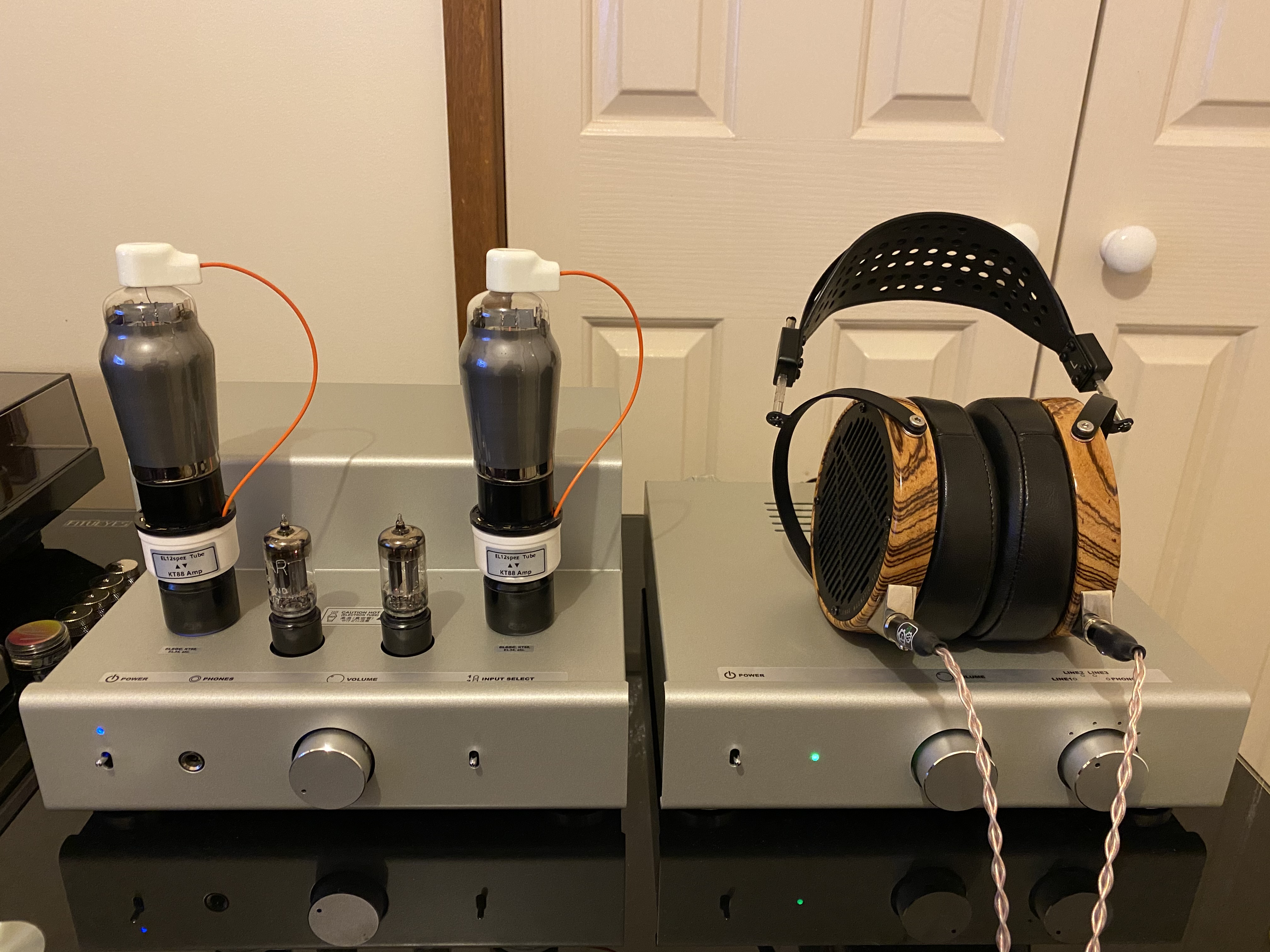
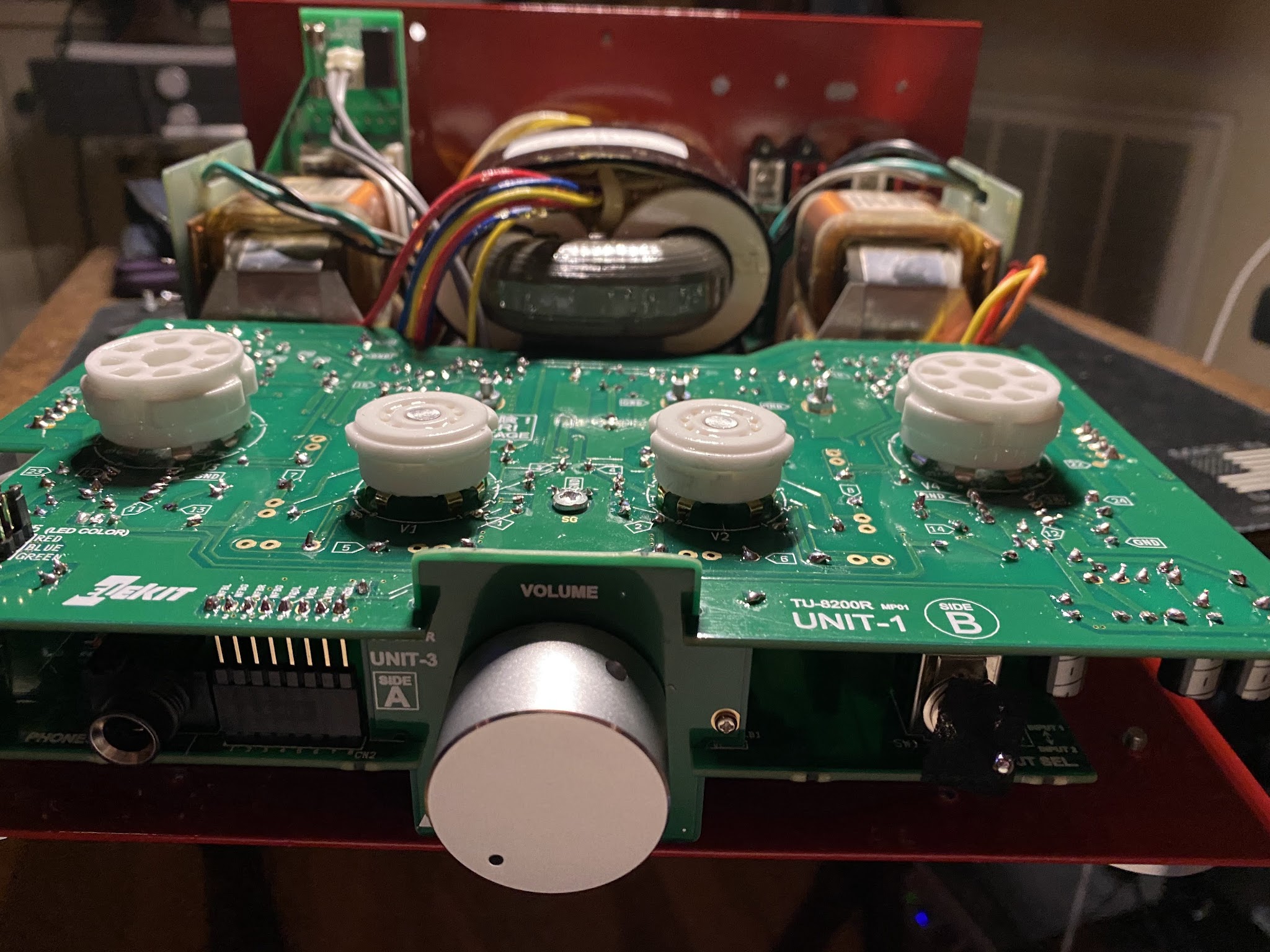
Based on the Elekit schematic Pin #1 and #8 are jumpered which is needed for EL34. 6L6GC does not use Pin#1 which has no effect on that bridge (for EL34). If I plug in 7027A into the socket many things can happen, including burned resistors, transformers, tubes, etc. Not worth risking another repair, I guess. Those tubes are different.
Some online information on comparing EL34 and 7027A tubes and possible swapping:
From http://www.triodeel.com/7027.htm:
Q.What about EL34's?
A.Simple. Install a jumper between pins 1 & 8 on the tube socket. However, do
NOT attempt to use 7027 after you've installed that jumper! Some folks who've used EL34's in these amps say they get better tone out of them by installing a variable bias control (the stock bias voltage on most Ampegs that use 7027, is a bit lean for EL34's), and by changing the screen resistors to 1,000 ohms instead of 470 ohms.
Note that a few of the early V-series Ampegs had no screen resistors at all! Unless you plan on going back to to 7027's (which you can't with the pin 1 to 8 socket jumper, anyway), you could install these right on the socket like a Fender or Marshall.
If you're going to do either of the above, I'd suggest strongly
putting a label on the chassis to indicate that it's wired to use EL34's, and that 7027 will NOT work.
If you've made the above changes, you can use 6L6 or 6550 as well, only caveat being that if you've installed an adjustable bias control, you'll want to adjust it when swapping between the various tube types. Installing a 1 ohm resistor between pin 8 and ground for bias metering (eg: 35 millivolts or .035V across the resistor will be 35 ma per tube) makes this procedure easier.
From http://www.ozvalveamps.org/strauss.htm:
Simply plugging 7027A's into sockets wired for EL34/6CA7's will result in at least burned-out screen resistors and a very quiet amp because the pinout is significantly different.
EL34 (left) and 7027A (right). Note the two internal 7027A connections between pins 1 and 4, and 5 and 6.
The EL34 socket will be wired with the cathode and G3 grounded, pins 1 and 8. The 1k5 grid stopper resistor is often wired between G1 and the No Connection pins 5 and 6. Screen volts are connected to G2 pin 4.
When we plug in a 7027A the stopper resistor is bridged by the internal link - not really a problem.
But the internal link from 4 to 1 will ground the screen supply. It's uncertain which will give out first, the screen supply resistors, the power supply, or in the unhappy case it's ultra-linear connected, the output transformer.  Sometimes we are forced to mod an output stage due to valve type unavailability. Converting 6DQ6 amps to use EL34's is one example.
But this apparent attempt to get more watts out needs more thought than just the base wiring. Apart from the plate-to-plate load impedance, the output tranformer power handling is bound to be exceeded and the power supply strained by any extra demand.
Just because it fits in the socket doesn't mean it's right.
Sometimes we are forced to mod an output stage due to valve type unavailability. Converting 6DQ6 amps to use EL34's is one example.
But this apparent attempt to get more watts out needs more thought than just the base wiring. Apart from the plate-to-plate load impedance, the output tranformer power handling is bound to be exceeded and the power supply strained by any extra demand.
Just because it fits in the socket doesn't mean it's right.