


You are using an out of date browser. It may not display this or other websites correctly.
You should upgrade or use an alternative browser.
You should upgrade or use an alternative browser.
Electricity Theory Thread
- Thread starter jenkinsontherun
- Start date


For some reason, I do not get notification from this thread, so I apologise for not responding sooner.I have a potentially loaded question.
How is an amp able to produce such precise swaps in voltage as to create music that is so detailed to our ears? Do we just have to accept that through decades of innovation, that technology is able to do this? Anything to note here?
Thanks.
Perhaps if you can explain the above, and form a question I can understand, then I shall try to answer.
jenkinsontherun
100+ Head-Fier
No worries. I realised that my question may be answered by learning the different amp classes. So, I'll watch some youtube videos and get back.For some reason, I do not get notification from this thread, so I apologise for not responding sooner.
Perhaps if you can explain the above, and form a question I can understand, then I shall try to answer.
jenkinsontherun
100+ Head-Fier
how many types of "signal" are there? I know the usb signal is digital, and the signal in the headphone cable is analog, hence two types from my understanding.
Edit: found an article, ignore.

Edit: found an article, ignore.
Last edited:
jenkinsontherun
100+ Head-Fier

Hello, I recently watched a youtube video explaining amplifiers.
Why is the above amplifier circuit bad? To me, who understands transistors as amplifiers, do not see any flaws with it. It does exactly what it's supposed to - takes a weak audio signal current at the base pin, which controls the amplitude of the large current across the collector and emittor pins.
The 8ohm resistor is the speaker.
Why is that bad? what are some flaws with it?
Thanks.
Last edited:
VNandor
500+ Head-Fier
- Joined
- Oct 17, 2014
- Posts
- 981
- Likes
- 611
Since nobody seems to answer:Why is that bad? what are some flaws with it?
The signal sent towards the speaker is going to have a big DC offset.
The negative parts of the waveform is being cut off at 0V. Actually, the signal will cut off at around 0.6-0.7V because the Base-Emitter needs this voltage to turn on and let the current flow.
The transfer curves of the transistor can only be considered linear if you don't operate on a large range.
While the current gain is constant, the voltage gain depends on the load.
I don't think this can be considered an amplifier circuit. The most basic amplifier circuits that use bipolar transistors (that I know of) are the common emmitter, common base and common collector amplifiers. You should look them up and see if you understand them.
Maybe you could watch some videos on how bipolar (or BJT) transistors work in a circuit? If you already consider a standalone transistor as an amplifier, you will never understand what the rest of the circuitry around the transistor does.
Last edited:
jenkinsontherun
100+ Head-Fier
There are some nice key terms which I no doubt will google.Since nobody seems to answer:
The signal sent towards the speaker is going to have a big DC offset.
The negative parts of the waveform is being cut off at 0V. Actually, the signal will cut off at around 0.6-0.7V because the Base-Emitter needs this voltage to turn on and let the current flow.
The transfer curves of the transistor can only be considered linear if you don't operate on a large range.
While the current gain is constant, the voltage gain depends on the load.
I don't think this can be considered an amplifier circuit. The most basic amplifier circuits that use bipolar transistors (that I know of) are the common emmitter, common base and common collector amplifiers. You should look them up and see if you understand them.
Maybe you could watch some videos on how bipolar (or BJT) transistors work in a circuit? If you already consider a standalone transistor as an amplifier, you will never understand what the rest of the circuitry around the transistor does.
But even connecting with the fundamental theory of how AC works, and how a transistor works, the "cut off" makes sense. In the reverse path of the AC cycle, the Base-Emittor does not flow backward but is instead turned off, hence the cutoff. At least in that circuit, as you say.
To begin with, the above is just a simplified circuit, in reality it won't work.
Hello, I recently watched a youtube video explaining amplifiers.
Why is the above amplifier circuit bad? To me, who understands transistors as amplifiers, do not see any flaws with it. It does exactly what it's supposed to - takes a weak audio signal current at the base pin, which controls the amplitude of the large current across the collector and emittor pins.
The 8ohm resistor is the speaker.
Why is that bad? what are some flaws with it?
Thanks.
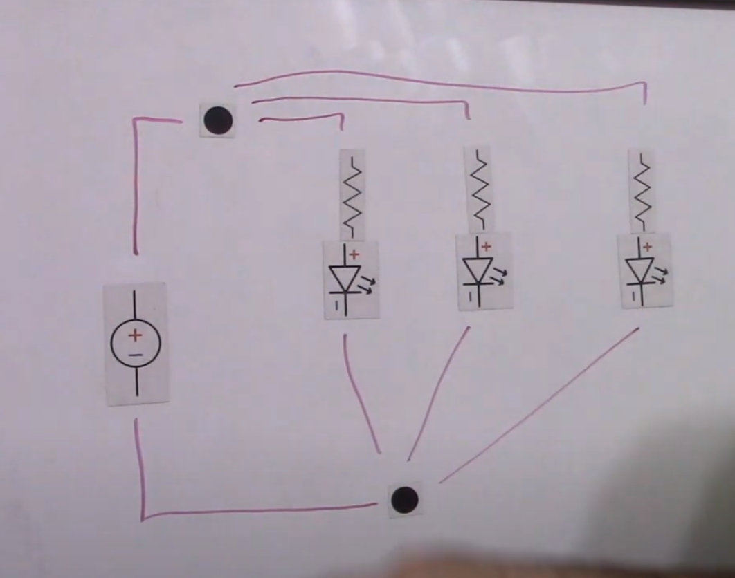
It is just a graphic showing current flow.
But before that, why do you say It is bad ?
Did you read anywhere that it was bad?
BTW, Sampled and Quantizated are both either digital or can be analogue.how many types of "signal" are there? I know the usb signal is digital, and the signal in the headphone cable is analog, hence two types from my understanding.
Edit: found an article, ignore.

Audio is Analogue, for transmission or recording, it can be origial format (analogue) or digital.
Even carrier wave formats such as AM/FM radio signal come under analogue.
jenkinsontherun
100+ Head-Fier
Materials/physics question:
How much does this have to do with headphone driver design? In my eyes, it has everything to do with it. Different diaphragm material has different point(s), obviously.
As was previously explained in this thread, the alternating signal to our headphones causes the diaphragm to move, creating sound pressure to our ears.
In a perfect world, or rather with the perfect material, we expect a perfect frequency response - dead flat.
In short - is resonance the main limiting factor for designing a perfectly flat headphone? Ignore pinna gain in this case, as that introduces many factors including human biology. "Flat at the driver" is what I mean.
Materials/physics question:
How much does this have to do with headphone driver design? In my eyes, it has everything to do with it. Different diaphragm material has different point(s), obviously.
As was previously explained in this thread, the alternating signal to our headphones causes the diaphragm to move, creating sound pressure to our ears.
In a perfect world, or rather with the perfect material, we expect a perfect frequency response - dead flat.
In short - is resonance the main limiting factor for designing a perfectly flat headphone? Ignore pinna gain in this case, as that introduces many factors including human biology. "Flat at the driver" is what I mean.
Yes it does have a lot to do with it, resonance is one of the major limiting factors.
For the record, a speaker or earphone is more like all the three sections in the video to be mounted on top of each other.
If you look at the SHM (simple Harmonic Motion) equations, you can see that it depends on Mass and Springiness.
The heavier the mass, the lower the Fundamental frequency.
Equally the springier the material, the lower the F frequency.
In sound transducers (speakers of any form), we have many resonances to deal with. There is the resonance of the diaphragm within itself , which bends and distorts the diaphragm.
There is resonance between diaphragm and the surround material, also resonances of the enclosure.
The goal is to make sure the speaker's resonance (fundamental or first) frequency is outside of the operating bandwidth.
One can see why Bass drivers, have more mass for the diaphragm and very soft surround material, and equally why HF drivers, have as light a diaphragm.
Also you can see why soft dome tweeters can actually reproduce HF even though they are made from a fabric!
In an earphone, there is the resonance of the ear canal too!
Ideally, a speaker would have very stiff diaphragm, with very soft surround material.
The soft surround ensures low (subsonic) resonance frequency, and the very very stiff diaphram (low springiness) ensures resonance frequency that occurs within the diaphragm is pushed well above audio bandwidth.
Take a look at Magico speakers, to see what lengths they go to to ensure resonance stays at bay.
https://www.magicoaudio.com/m-series-m6
https://www.magicoaudio.com/enclosures
https://www.magicoaudio.com/drivers
Last edited:
jenkinsontherun
100+ Head-Fier

pretty surprising find given what I assumed to be basic concepts
SilverEars
Headphoneus Supremus
- Joined
- Sep 18, 2013
- Posts
- 15,836
- Likes
- 7,349
I recommend you take some basic AC-DC electronics, and build some electronics kits to get a more concrete feel of it. If you have some math background, move onto more advance stuff like advance circuits and transistors.
Users who are viewing this thread
Total: 1 (members: 0, guests: 1)
