Quote:
Originally Posted by fran /img/forum/go_quote.gif
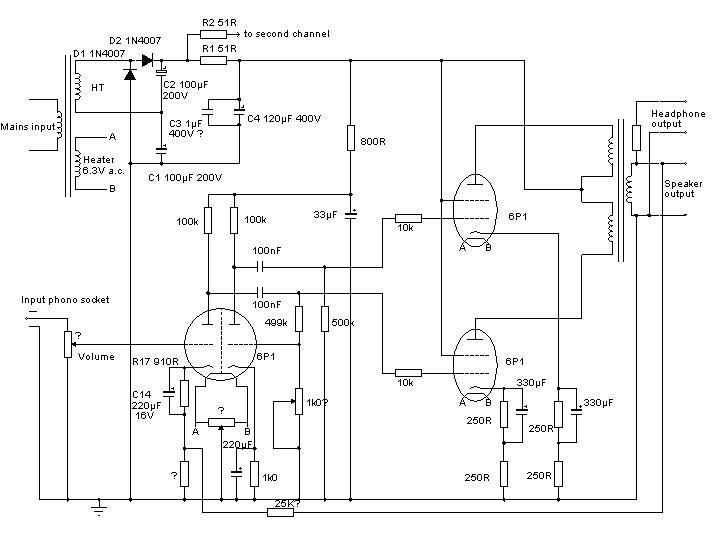
Ok, I'll have to check in more detail later but:
1. double triode tube is 6N1 rather than 6P1
2. The trim pots for grounding the heaters was 50R, but I have replaced these with 2 x 100R to ground on all tubes (although I might just go to DC anyway)
3. The headphones output is taken before the output transformer through a 4K7 resistor. eh, I think anyway!
4. I have added in another 2 caps 220uF/200V in parallel with each of C1 and C2
Could you ask your Dad are the 2 other pots for biasing the output tubes? They read in the order of 50K (from memory) and would he have any idea of what they should be at, or how to adjust them (eg what do I measure whiole adjusting the pot?)
Fran
|
The reply from my Dad...
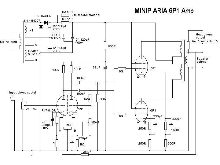
1Oops of course it is, I'll change the schematic!
2OK I'll add the 50 Ohm value to the schematic (which represents the
original amp rather than any upgraded version). The idea of the trim pot is
of course to balance the heaters as ± 3V rather than a single ended 6V to
cancel the hum. Replacing the pots with fixed resistors removes the ability
to trim this to compensate for any imbalance of pickup from the 2 ends of
the heater to the cathodes. However the original arrangement seems dangerous
to me if there are really 2 pots on a single heater supply, as if one is
adjusted to one end and the other to the other end the heater supply would
be shorted out probably resulting in burning out the pots.
3The headphone output seems rather surprising! 4k7 is a rather high
value for connection to the speaker output in the way I thought it was but I
can't see a sensible place in the circuit to connect it on the high voltage
side of the output and it would need a capacitor in series too to avoid
being dangerous. If you can work out any more details I'll update my
schematic.
4 I agree that the total power supply reservoir capacity seems a bit
low for a hi-fi amplifier, I would be inclined to add extra capacitance in
parallel with the 120µF 400V capacitors and the 33µF on the triode anode
supply rather than adding to the 100µF voltage doubler capacitors due to the
increased surge load that extra capacitance here places on the rectifier
diodes, particularly at switch on.
5I'm not a valve amp expert but as far as I can see the second pot is
intended to balance the drive to the 2 output valves. I guess that the
attenuation produced by the pot and fixed resistor should be equal to the
gain of the second triode so that the signals at the grids of the 2 output
valves would be equal and opposite. If I am correct then setting up would
require a signal generator and scope or a.c. voltmeter. Actually thinking a
little further I guess it is not the grid voltage which would be matched but
the a.c. anode currents of the 2 output valves so the best place to measure
might be across the un-bypassed part of the cathode resistors for the 2
output valves. So I'd put a sine wave signal in and measure the amplitudes
at the top of the 250 Ohm resistors (or for that matter on the cathodes of
the 2 output valves) then adjust the pot to make them equal.
And his updated schematic....