Dynalo (Rev.C) construction thread
May 6, 2005 at 3:27 PM Post #17 of 188
Quote:

Originally Posted by steinchen
Glimmer caps are in fact Mica caps. [...]


oh... just learned another cryptic diy word... thanks!
 
May 11, 2005 at 5:42 AM Post #18 of 188
Now that I've finally found some free time
rolleyes.gif
, I'm ready to order parts for a couple of boards.

Could some kind soul recommend sockets for transistors, preferably with a mouser or digikey part number? Something similar to what dgardner uses here would be great.

Quote:

Originally Posted by amb
Actually I think it's just the opposite... you would use less capacitance if the gain is higher.


You can stop thinking - you're right.
smily_headphones1.gif
 
May 11, 2005 at 6:06 AM Post #19 of 188
i dont have a mouser or digikey number but any snap off single row socket set will work. they usually come in 40 pin rows
smily_headphones1.gif


check the pdf catalog's of the stores to find em, heaps better then searching the sites
 
May 11, 2005 at 6:12 AM Post #20 of 188
Quote:

Originally Posted by SnoopyRocks
Could some kind soul recommend sockets for transistors, preferably with a mouser or digikey part number? Something similar to what dgardner uses here would be great.


As far as I could tell the TO-92 transistors on his board are all on break-apart SIP sockets (like these). I am curious about the ones the dual-JFETs are plugged into, however.
 
May 11, 2005 at 6:14 AM Post #21 of 188
Quote:

Originally Posted by SnoopyRocks
Now that I've finally found some free time
rolleyes.gif
, I'm ready to order parts for a couple of boards.

Could some kind soul recommend sockets for transistors, preferably with a mouser or digikey part number? Something similar to what dgardner uses here would be great.

You can stop thinking - you're right.
smily_headphones1.gif


Mouser socket link
I think you can order those in strips with different numbers of pins. Either way break off the number you need.

I believe the sockets Dan used for the dual fets were old and obscure. He posted about them somewhere. I havent checked spacing, but you might be able to use a row of 4 and a row of 3 of the SIP sockets.
 
May 11, 2005 at 1:50 PM Post #23 of 188
The sockets that Dan used for the FETs are actually Zig Zag sockets, something like Digikey ED2220-ND (MillMax). I got a couple of samples of the 28 pin version of these, and they are easy to cut apart into 7 pin sockets, and fit better than 2 rows of SIP sockets do. The SIP sockets I used are the MillMax, Digikey part ED7064-ND (64 pin). I like these better than the other SIP sockets I have tried (Aries).

On Dan's boards, the middle of the 3 pins for the FETs does not have a hole, so really you need (2) 3 pin (2-1) sockets, or you can drill a hole for the middle pin, or just clip the tail on that one.
 
May 11, 2005 at 4:14 PM Post #24 of 188
Quote:

Originally Posted by Pars
The sockets that Dan used for the FETs are actually Zig Zag sockets, something like Digikey ED2220-ND (MillMax). I got a couple of samples of the 28 pin version of these, and they are easy to cut apart into 7 pin sockets, and fit better than 2 rows of SIP sockets do. The SIP sockets I used are the MillMax, Digikey part ED7064-ND (64 pin). I like these better than the other SIP sockets I have tried (Aries).

On Dan's boards, the middle of the 3 pins for the FETs does not have a hole, so really you need (2) 3 pin (2-1) sockets, or you can drill a hole for the middle pin, or just clip the tail on that one.


I just cut the zip socket to size then turn it over and push the middle pin out of the socket body with a nailset.
 
May 11, 2005 at 7:33 PM Post #26 of 188
Quote:

Originally Posted by Pars
The sockets that Dan used for the FETs are actually Zig Zag sockets, something like Digikey ED2220-ND (MillMax).


Thanks for the pointer!
 
Jun 10, 2005 at 11:57 AM Post #27 of 188
Finish my first DIY headamp, but questions is how to measure and adjust.
tongue.gif


I follow measure with this diagram, I've adjust the voltage as this.

Dynalotest.bmp


But, I measur the output there were different voltage from left and right.

Any one can help? Thanks!!!
 
Jun 10, 2005 at 3:27 PM Post #28 of 188
Quote:

Originally Posted by palchiu
Finish my first DIY headamp, but questions is how to measure and adjust.
tongue.gif


I follow measure with this diagram, I've adjust the voltage as this.

Dynalotest.bmp


But, I measur the output there were different voltage from left and right.

Any one can help? Thanks!!!


When you say the output was different, I assume you mean the DC offset on the output, measured with inputs shorted to ground? What readings are you getting here?

In a discrete amp such as this, irregardless of how well you match everything, there will be some difference between channels. If you are measuring 10mV or lless on each channel without the servo opamp installed, you are in good shape. Otherwise, it may be necessary to change out LEDs, put a pot in parallel with the 500 ohm input resistors, or other steps in order to bring the offset down. The voltage measurements that you showed on your drawing are only a guideline to determine proper component and amp operation. Getting DC offset as close to 0 mV as possible is the real goal, and should be the predominate measurement that you use when adjusting anything in the circuitry.
 
Jun 11, 2005 at 3:13 AM Post #29 of 188
Jun 11, 2005 at 4:54 AM Post #30 of 188
Quote:

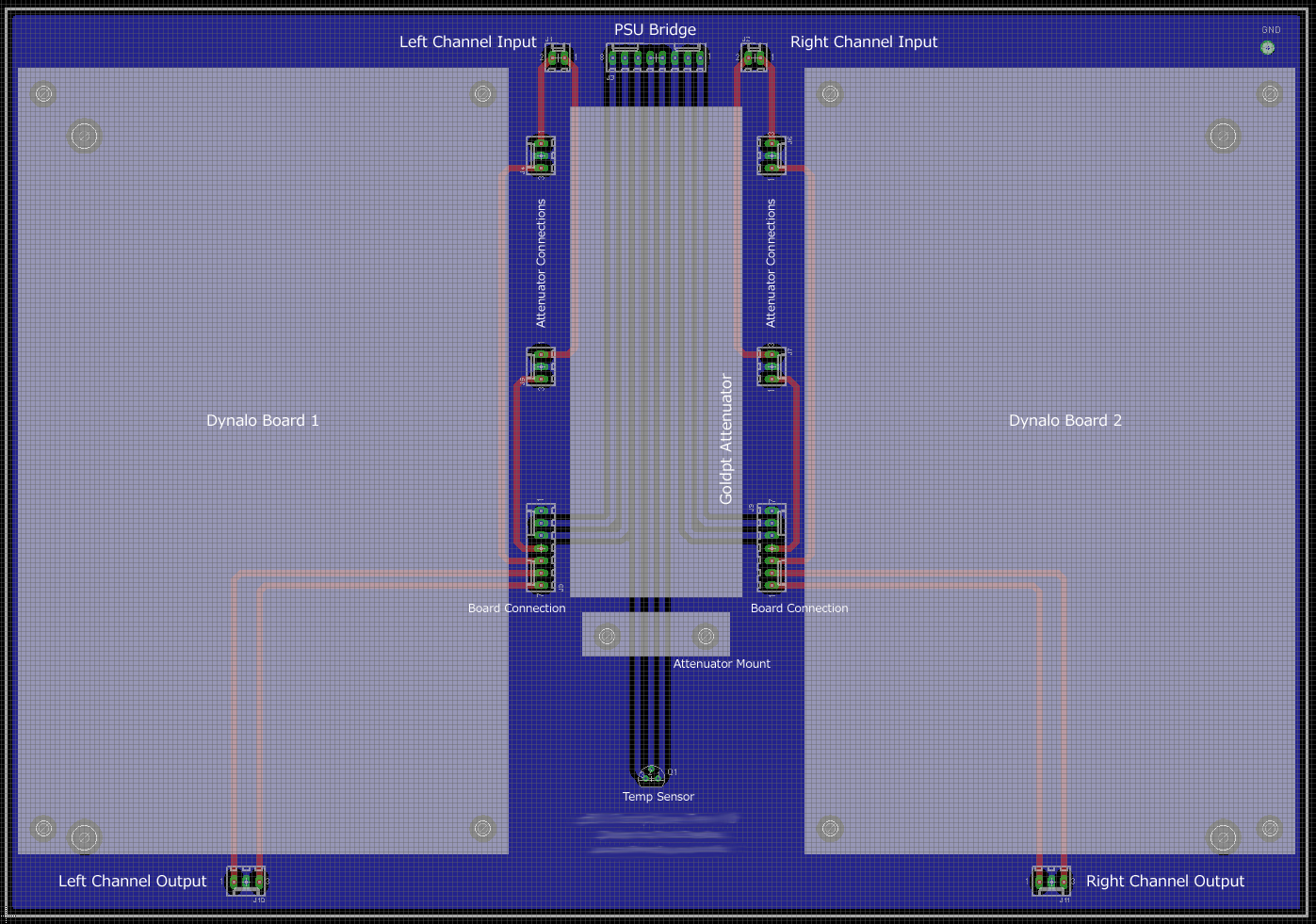
Originally Posted by dgardner
Dynalo - Detailed Construction (dgardner 5-7-2005).doc (2.59MB)
Dynalo - Detailed Construction (PARS Edits).doc (2.57MB)
Dynalo - Detailed Construction (STACKOFHAY Edits).doc (2.61MB)
Dynalo - Operating Points.pdf (131KB)

We are now entering the community editing phase of the project.
biggrin.gif
Thanks to everyone who has contributed to the edits so far. I fear this will never be completed if I don't just post is here raw and let everyone run with the edit process.


Great job Dan! You might want to add that it would be recommended to do soldering with some form of vise, e.g., one of those Panavise circuit board holders.

Not a necessity but would make putting components on the board Extremely easy! Also, it might be useful to mention that you can use masking tape to hold chips or components to the board instead of bending the leads to make them stay put. I'm always weary that by bending leads I might accidentally short items by accident. Its also easier to put on since tape can be placed to hold many items at a time (and could be reused when having to put new items in). Just a suggestion to aid newbie's out
smily_headphones1.gif
 

Users who are viewing this thread

Back
Top