


EggofSound
100+ Head-Fier
Where can I get the Lurker's add-on and how is it installed on the DX220?
Here you will.
https://lurker00.github.io/Firmware-for-iBasso-DAPs/
Where can I get the Lurker's add-on and how is it installed on the DX220?
Thanks for directing me to the file.
Thanks for directing me to the file.
Is there a way to download and transfer from a Mac ?
Is there also a way to do this via WiFi option without the SD card?Check the link above. There are two options. The first is for Windows, the second allows you to make a bootable SDcard:
- DX220-A8.1-L1.18b2-sdupdate.zip - to use with DX220-bootable SD-card, which can be prepared under any OS.
Is there also a way to do this via WiFi option without the SD card?
No, that would probably have to be done by iBasso directly. This is an add on that Lurker creates out of goodwill to the community. We are fortunate to have it all.
I also have a Mac, but I install it in Windows under Bootcamp. However, I know that many people use the SDcard method effectively.
Thanks for the clarification.Using an SD-card is easier, but it is also possible on a Mac.
Please read it.
[DX220FirmwareUpdater] link-> [the description and instruction] link-> An instruction for MacOS users
After that, I think that the question of FW etc. is appropriate for the thread of DX220.
----
I'm sorry. I made a mistake in the quote destination.
The MedAs promised a bit of my experience. Well, firstly, the potential for improving amps is significantly limited and quite expensive. But the fact that mad craftsmen can significantly improve the sound of their ibasso devices is undeniable. Okey, let's go. So the capacitors were replaced in the power supply. It was 1000uF×2 6.3 v nichicon fw. It became 1500 uF×2 6.3 v organic electrolyte. And capacitors in the aisle. It was 22uF×4, became 47uF×4 16v (Elna silmic 2 or nichicon es nonpolar green)or 100uF×4 6.3 v nichiicon fine gold. The power supply is considered you need to assign the capacity. Well, actually in the aisle will not interfere with 100uF, although 47 well. But I still might try 100uF silmic2. Soft absorber EMI I have not installed, expensive and nowhere to buy fast. Tried to bypass power and aisle. I believe that this is not appropriate. Although power can be shunted. A aisle does not need to be shunted and even probably harmful. And not fit all of these shunts there. Fine gold excellent capacitors if you like warmth deep and soft bass, not straining high frequency and high-medium frequency, low male vocals and soft female vocals. Silmic2 is good resolution, fine high frequencies but weak bass and bright high-mid frequencies. Nichicon es excellent resolution in all frequency ranges, faster and deeper bass than with silmic2, but less deep than with FG. I'm still on the ES. But now I am listening to the player more often with TFZ galaxy t2. T2 softer headphones and cable I have a hybrid copper-copper-silver plated 2.5 mm. But with Tfz tequila 1 player sounds a little bright. Most of all I liked the combination of tequila with FG. Or rather with tequila es is also good and very atmospheric, but a little bright. Bright also with tequila and silmic2.


It is an extreme example to EX but...
The removed parts can be used in a drastic (in some sense, safest) operation if they are not used.
The body of the tantalum cap is scraped little by little from the middle with a nipper, and removed with the pad attached to the Land.
Cut the foot of LDO (LP5907) from the base of the body.
Finally, heat is applied directly to the Land to remove the Pad (lead) of the Land.
I did this with the DX200.
It is a rough method, but you can work in less time without adding heat to other parts as much as possible.
About temperature
Since I use a soldering iron, I ignored the reflow temperature of the data sheet, but instead I soldered in a short time.
In the case of SS-47 0.6mm, it melts at 210 degrees.
The SMD 1206 (22uF, 72uF) was set at 220-240 depending on the location.
The SMD 1311 (100uF, 220uF) was set to 260-280 degrees.
In the case of soldering irons, the temperature drops approximately 30-50 degrees from the set temperature during soldering.
The side where the wide pattern is drawn needs high temperature.
The spare solder is not the actual installation but points to the Pad of Land or Tantalum Cap.
In the image of the coating, it is a very thin 1 second (SMD 1206 is one touch) in a short time.
Temperature calibration is also required for heat guns and solder irons that can be set in temperature.
In the case of soldering irons in particular, the temperature difference due to the used tip is severe.
In addition, there are products that require temperature calibration such as HAKKO.
(My FX-888D has a difference of 50 degrees by default)
After that, PPS (ECHU) is weak to heat and easily broken (deforms)
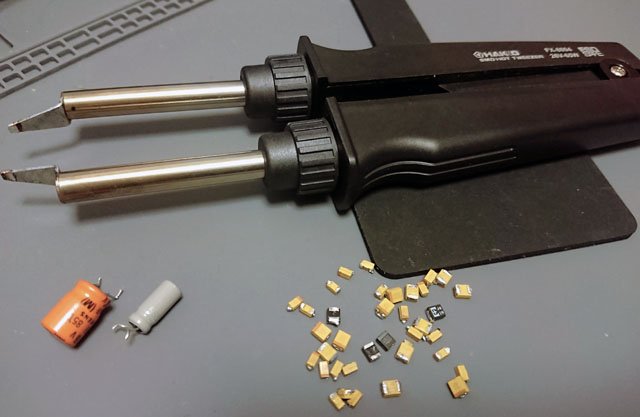
I think that tweezers should avoid using metal and use the tip of ceramic type.
In the case of AMP7 and AMP8, I think that some people use an electric tweezer.
The pattern of the power supply line is wide and the signal line is thin, so the signal line side is lifted first.
Stop using the tweezers that are separated (floated) on one side.
If you pull it, the Land may come off easily.
AMP7 and AMP8 are still good because of the thickness of the tantalum cap pattern.
AMP1 is different from AMP7 and AMP8, and it is not possible to recommend the tweezers because Land is peeled off easily because of the large number of circuits.
(The same may be true for AMP1 MkII)
It's too convenient and comes with risks...
The Med
The Amp 8 Mod described by Whitgar appears to use only SMD caps for the replacement parts. Why did you choose large electrolytic for your replacements?
Would you be kind enough to send high res photos of before and after the AMP8 EX Mod so I see exactly what is removed from the stock board and what is replaced from each side?
I really need a step by step road map with photos then I know I can do it as I have the skills, microscope, tools and experience building kits with SMD components etc. I like your approach of nipping off the native tantalum caps before desoldering the component pads. A few questions below:
I know Whitigir responded to this before but for final clarification, are the parts listed below all that are needed for the AMP8EX mod?
- Are parts listed below all that I will need? How many of each do I actually need to cut costs or is just 1 spare for each enough in case one flys off the table and gets lost? Is the first part listed by Vance (voltage regulator) used for the AMP8 or main SX200 pcb “https://www.mouser.com/ProductDetail/595-LP5907MFX-3.3NPB 2x of these, buy 4x for spare”
https://www.mouser.com/ProductDetail/80-T543B107K010TE150
12x of these, you buy 14X if spares are needed.
https://www.mouser.com/ProductDetail/80-T527I476M10ATE200
7x of these , buy 10x or so for spares
https://www.mouser.com/ProductDetail/80-T527I226M10ATE200
10x of these, buy 12x for spares
https://www.mouser.com/ProductDetail/80-T543B227K6AHW35
3x of these, buy 4x for spares
https://www.mouser.com/ProductDetail/647-RNE1C471MDN1PX
1x of this, 2 for spares
https://www.mouser.com/ProductDetail/810-IFM10M25BB300200
Steps:
Thanks for the help
- It looks like only one row of larger electrolytic caps on the native AMP8 board are just removed and only the prexeisting SMD caps just swapped out for new SMD caps except for the nichicon 470 uf? Where is the nichicin 470 uf cap placed? I don’t have the amp to look at yet.
- https://www.mouser.com/ProductDetail/810-IFM10M25BB30020 Is this film RFI shield also used on the AMP8 EX mod and where are they positioned? Is the film tacky or glued on? A photo would be great as this is the most expensive mod part.
- Is Part 3: Ground path Return Mod really necessary for the EX mod? What grit number sandpaper and what type is needed ? From the photo it looks like only the mounting posts on the chassis are sanded not the screw holes on the Amp board pcb?
Dan
The Med
The Amp 8 Mod described by Whitgar appears to use only SMD caps for the replacement parts. Why did you choose large electrolytic for your replacements?
Dan
Yes, the beauty of DIY ! The freedom to do whatever you want, and as long as you don’t loose the ballsWhitgar showed the index of DX200EX.
You also have the freedom to DIY the sounds you want.
Music (audio) is not perfect for everyone.

Yes, the beauty of DIY ! The freedom to do whatever you want, and as long as you don’t loose the balls

I feel like this.
Wick: 0.8mm (HOZAN is recommended if available)
Flux: good BS-95B
Flux cleaner: good BS-T20B
Spare solder: good SD-51(SD-62)
You do not need a cat.
Indeed. I like 99% pure isopropyl as it doesn’t leave stains.I agree, I do not need a cat, since I have one, which looks almost the same as yours)).
Oayide is good solder wire, I've would have used WBT and Cardas as well.
Also to note (if anyone performs this upgrade) - clean off the flux completely with some FIux OFF cleaner and then with isopropyl.


