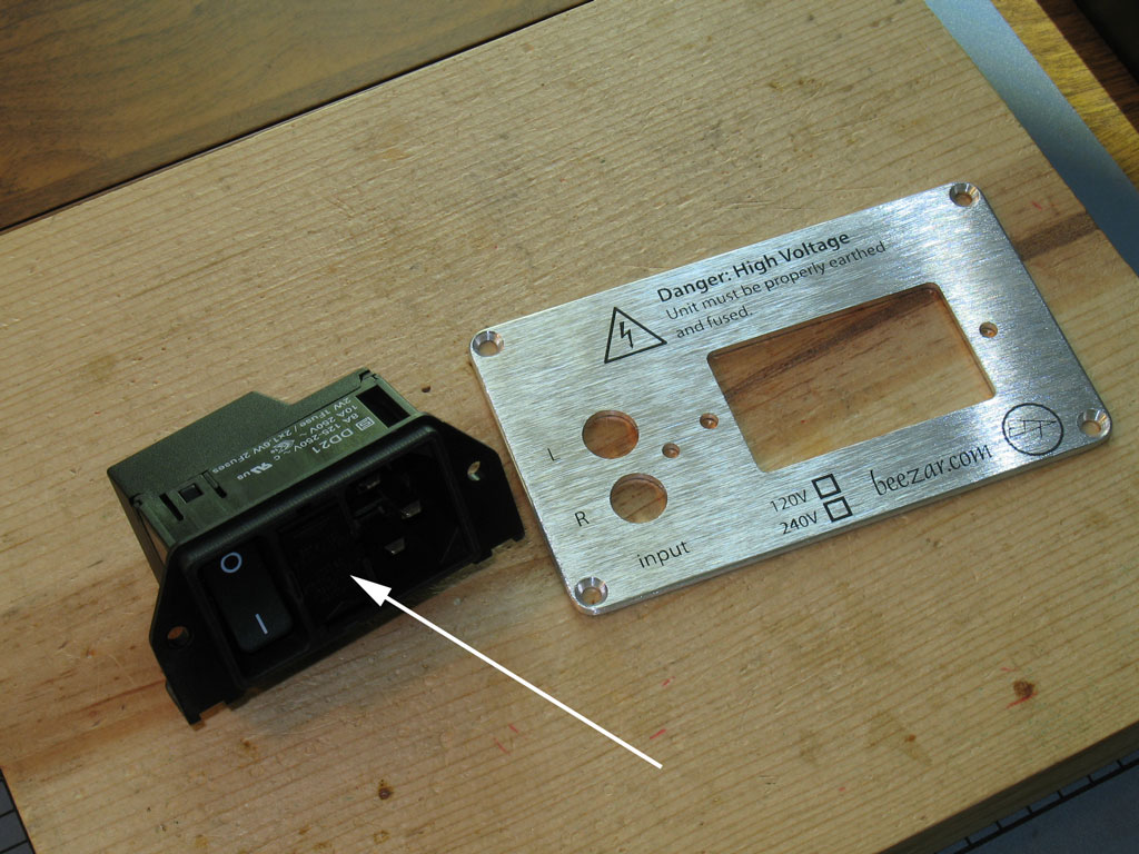
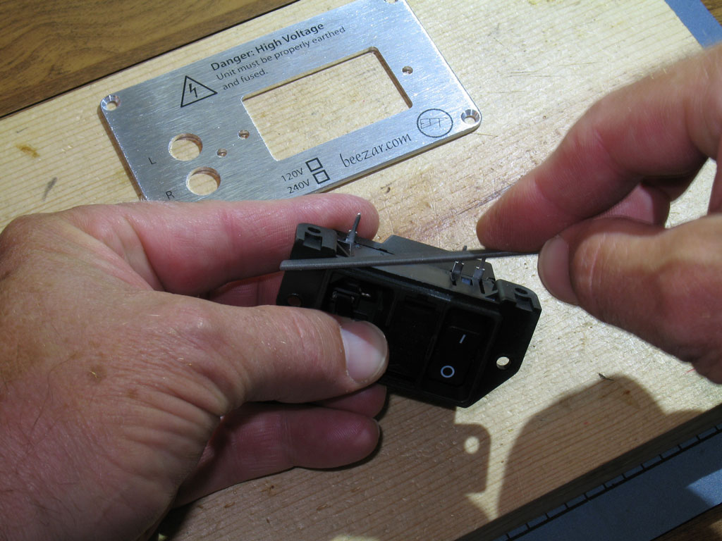
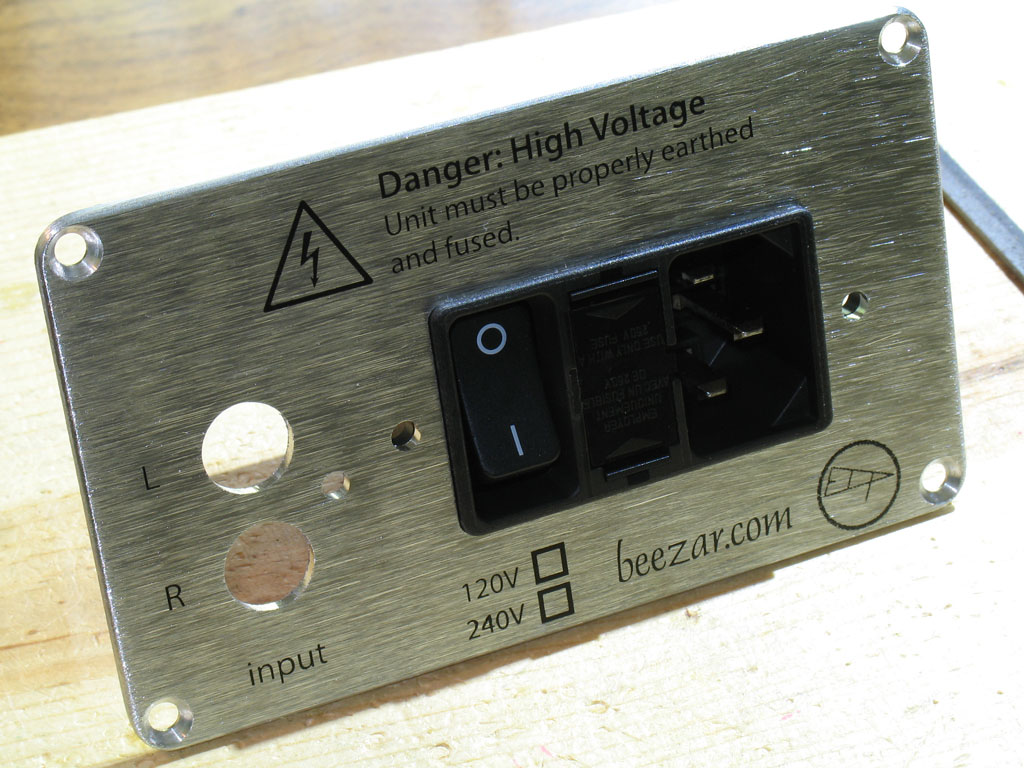
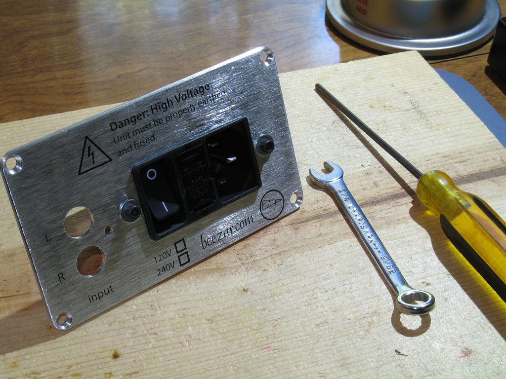
Dsavitsk/Beezar Torpedo Build Thread
Sep 9, 2011 at 2:20 AM Post #18 of 854
parafeed! :D

14inch long?!! :rolleyes:

I hope I would still be able to afford the kit... :)
 
Sep 10, 2011 at 11:19 AM Post #19 of 854
Step 23. -
Next up is the IEC inlet!  Pictured below are the 3 parts that make up the IEC inlet.  Note that these must be ordered separately! (The custom case back plate is also shown.)

1) the IEC inlet and housing, 2) the fuse drawer, and 3) fuse and spare.
 
To assemble the fuse drawer into the IEC, place the spare fuse either in the filter drawer or the IEC (in the IEC is shown):

 
Next, place the primary fuse should be inserted into the fuse drawer (it won't sit in the IEC without the support of the fuse drawer):

 
Snap the filter drawer in place.  Shown below is the filter drawer snapped in place alongside the back plate:

 
Next we'll "snap" the IEC into the back plate and screw it into place.  The reason we do this at this point - instead of simply soldering the IEC onto the PCB - is that there is some play, backwards and forwards, with the PCB and the case fit-up.  This was done because all of the parts are essentially locked into place once soldered onto the PCB.  Over a length of 14 inches, this can cause huge issues if the parts don't fit perfectly or are not soldered into place exactly in alignment.  For that reason (and also because the solder leads on the IEC are so big), there is some play in the IEC leads, its pads, and its PCB screw holes (there are two of those).  To account for this and lock the perfect alignment in place from front to back, we'll mount the IEC onto the back plate, first.  Once that's done and it's bolted into place, then we'll solder the IEC - back plate and all - to the PCB. 
 
The custom Beezar/ECP Audio case design includes a rectangular opening with radiused corners for the IEC.  This opening is machined perfectly for the IEC design drawings.  Unfortunately, being a molded phenolic, there are variances in the rectangular area on the IEC.  Because the entire rectangle is exposed without any sort of cover, frame or other finishing attachment, we left no tolerance gap on the back plate.  As a result, some IEC's will probably fit snuggly without an issue.  Others may need a slight bit of filing to fit.
 
If yours doesn't fit perfectly (mine didn't on this build, either), wedge the IEC into place on the back plate as best you can.  Hold the assembly up to a light and you'll easily be able to see where there's clearance and where's there is none.  Remove the IEC and using a small flat file, file enough off of the high spots until you get it to snap in place:

 
After some slight filing (careful - it is very easy to file the plastic/phenolic!), we have a perfect fit:

 
Now that it's snapped into place on the back plate, we'll screw it flush to the back plate using the familiar 4-40 screws, washers and nuts.  Here's the view from the back with the screws in place and the IEC firmly mounted to the back plate:

 
On the inside, we finish off the cap screw assembly with a flat washer, a lock washer, and nut:


Sep 10, 2011 at 11:31 AM Post #20 of 854
To install the IEC/back plate assembly to the PCB, we "roll" the IEC-back plate assembly onto the back of the PCB for preparation of soldering into place.  There are several screw holes that need to be screwed down, first.  Again, remember - once we solder it, there's no moving it again.  So, we get the alignment correct and mount the screws, first. Shown below is one of the two screw mounting holes for the PCB - there's one on each side of the IEC inlet that screws it to the PCB.  Also indicated is a single screw hole for the RCA jack assembly that screws the RCA jacks to the back plate.

 
Here we see the back plate around the RCA jack assembly.  The RCA jacks actually have a concentric ring that's larger than the RCA jack barrels themselves.  The holes in the back plate account for this, so be sure that the holes are fit around those larger rings and not mis-aligned ... before you screw the screw into the jack assembly.  On the first couple of builds, I actually tapped this assembly for 4-40 threads.  However, it turns out that the white plastic is soft enough that you can screw in a regular 4-40 screw and it will self-tap on its own.  (You can see some of the plastic chips in the previous pic as a result of doing this.):

 
Finally!!  Here we see the bottom of the PCB with the IEC pins (3 of them) ready to solder.  Also shown are the screws that mount the IEC to the PCB (same flat washer, lock washer, and nut as used on all the other screws):

 
Sep 10, 2011 at 11:46 AM Post #21 of 854
Step 24. -
The final step for the PCB is the wiring, of which there is very little.  This consists of the ground wire for the Alps pot, and the safety ground for the PCB.
 
The pot ground wire is straightforward.  Unfortunately, I should tell you that it would be much easier to do right after you install the pot to the PCB and before you install the OTs.  Nevertheless, there is just enough room - with the right screwdriver - to install the ground wire at this point in the build sequence.  Cut a wire slightly longer than the distance from the PCB to the top pot screw as shown.  After soldering the wire into the PCB and unscrewing the pot screw, loop the other stripped end of the wire around the pot screw shaft and screw the screw back into the pot:

 
Step 25. -
Next, install the safety ground wire at the back of the PCB.  To do this, cut and strip both ends of a wire about 2 inches long.    You can probably get away with it being much shorter, but there's no issue with looping it under the PCB and it's a lot easier to have a wire that's too long rather than one that's too short.
wink.gif
  On one end of the wire, solder a lug for a 4-40 screw as shown.  You can use a crimp-style lug, but since this is for "safety," please solder it, too.  Once you have that done, solder the other end of the wire by placing it into the pad on the bottom of the PCB.  The large hole in the PCB will allow us room for a screwdriver from above:

 
HEY!!  We've finished the PCB!!
 
Sep 10, 2011 at 12:46 PM Post #22 of 854
Step 26. -
Clean the PCB!
 
It's a little unusual to detail cleaning the PCB like this, but remember - HIGH VOLTAGE.  There's more force behind higher voltage and it will "jump" across connections more readily than the typical SS or hybrid amps that are built on a PCB.  So, IMHO, cleanliness is part of the safety.  You don't want any of that old flux and soldering dirt to create enough of a connection that might encourage the voltage to arc across a set of leads.  So, we're going to clean this PCB well and show you how to do it easily and cheaply.
 
Below we see the PCB with my essential tools for cleaning:

Next to the PCB we see a small butter bowl and a toothbrush.  Next to that is a bottle of the alcohol that I use for cleaning.  This is 91%, but is less than a dollar at Walmart (last time I checked).  A quart will last you a long time.  I've tried several chemicals that they make supposedly specifically for solder flux, but none of them clean as well as 91% isopropyl and most of the other chemicals emit vapors so bad you need to use them outdoors.  So, I stick with the alcohol.
 
Anyway, I pour an inch or so into the butter bowl and use the toothbrush to apply the alcohol across the entire PCB.  Use the brush to scrub the places where the flux is really thick:

 
The alcohol dissolves most of the flux right away.  However, something a lot of people don't mention is that the dissolved flux-alcohol mixture doesn't go anywhere unless you try to drip all of it off of one side of the PCB.  That's not a very good strategy, so I use paper towels to pat up the dissolved mixture:

 
So we're done, right?  NO! Take a look at this:

That white stuff you see is the dried-up flux that was deposited after the alcohol evaporated.  So that means a single dousing of the alcohol, toothbrush, and paper towel didn't get it all.
 
In reality, it takes several rinses.  It took me six times to get the PCB to an acceptable condition:

That sounds like a lot, but honestly, it was probably 15 minutes or less.  The alcohol evaporates so quickly - especially when using the paper towel - that multiple rinses go very quickly.  In the pic above, you may be able to still spot some white stuff around the solder joints, but all-in-all, it's pretty clean and good enough for me.
wink.gif

 
Sep 10, 2011 at 1:20 PM Post #24 of 854
Step 27. -
Final Assembly!
 
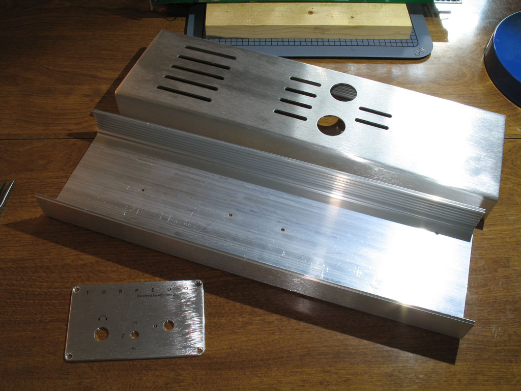
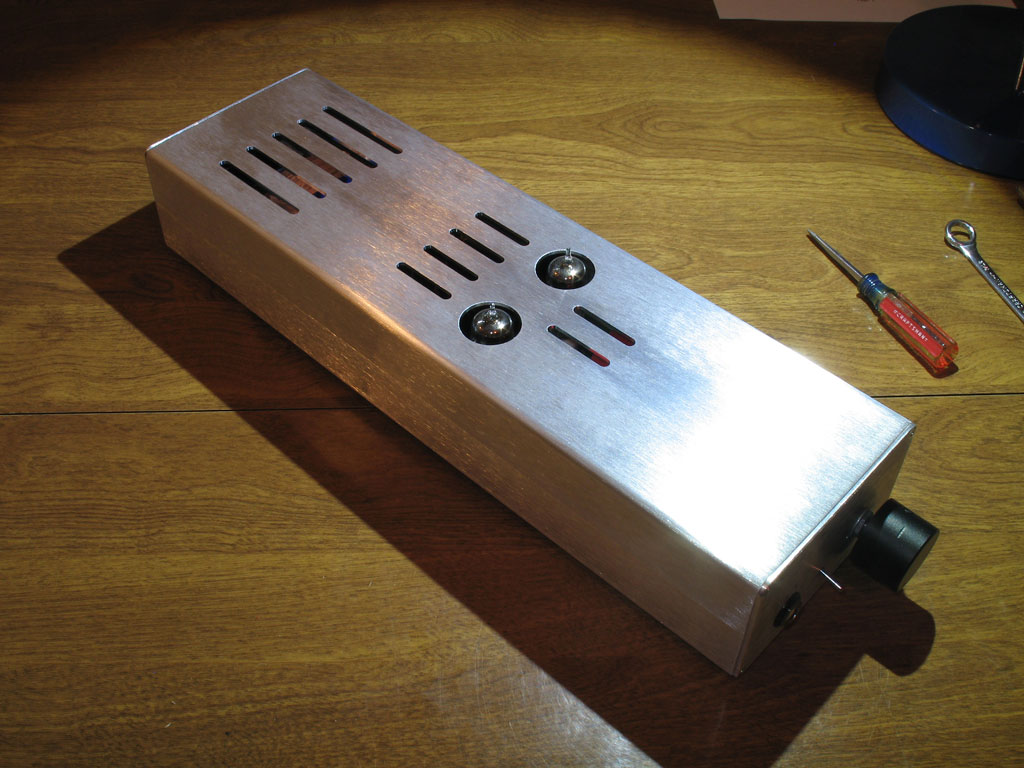
Below we see the custom Beezar/ECP Audio case from Context Engineering.  The case comes in two equal halves.  This was a primary design selection for the Torpedo.  That's because the transformers and other part heights require that the case depth is enough that the tubes barely stick out of the top.  IOW, you can plug a pair of tubes into the amp while it's cased up, but getting them out is a different story.  With the Context case design, however, you can simply unscrew the top two screws of each end plate and simply lift off the top of the case.
 
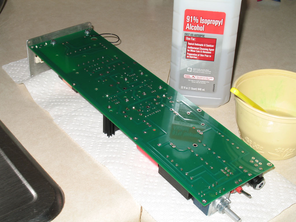
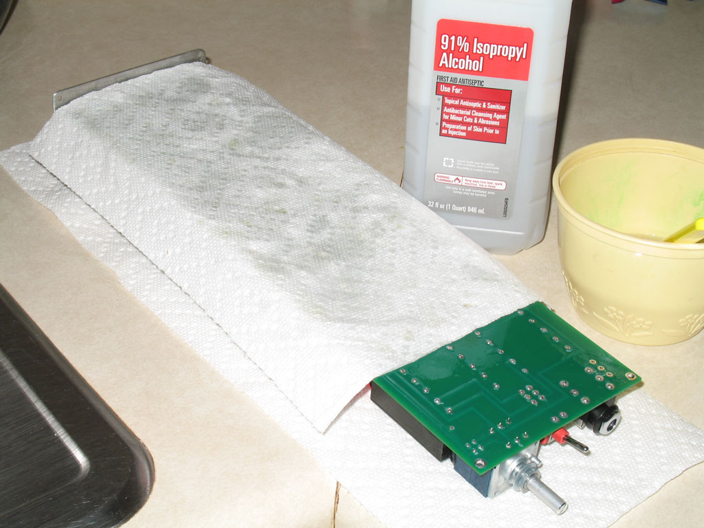
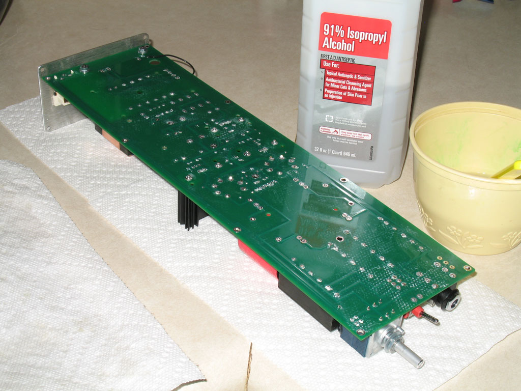
Right now, the custom cases are bare-unfinished aluminum.  That may change if the amp is a great success with you guys, but in the meantime, it means more cleaning.  Unfortunately, I am not happy with the finish condition in which Context supplied the machined cases.  The reason being is that there are metal chips and dust everywhere.  As with the PCB above, this is HIGH VOLTAGE and the last thing you want around HIGH VOLTAGE are a bunch of conductive metal chips and dust.  So please-please-please, for your own safety, clean these things thoroughly.  I took a small screwdriver with a paper towel folded around its tip and ran it the length of every slot - including the slots that are used to fit the top and bottom case halves.  In addition after that, I gave the insides a thorough wipe-down and finished by running paper towel/rag around the inside of every machined hole.

 
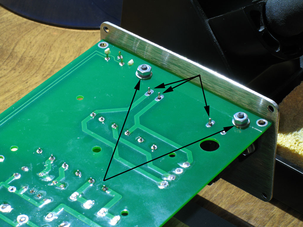
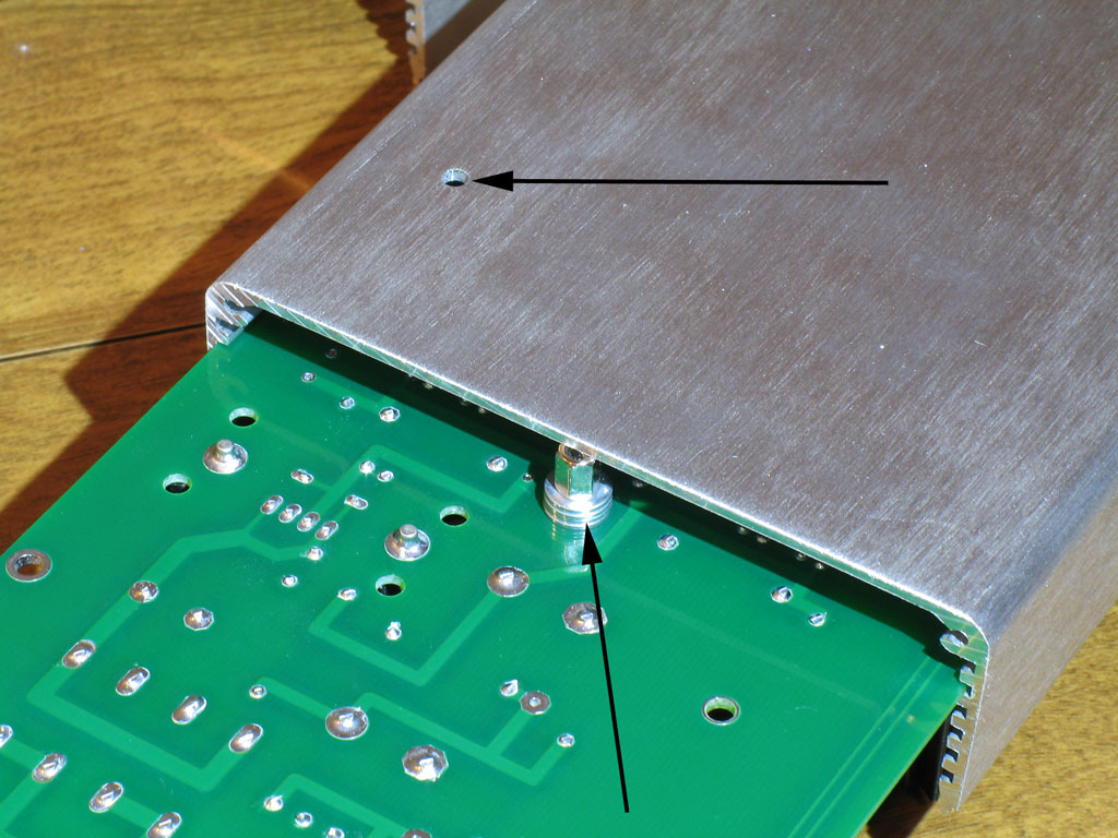
The first thing we need to do after cleaning the case parts is to install the standoffs onto the PCB.  Note in the pic above that there are four 4-40 size (1/8") holes.  The one close to the corner in the back is for the safety ground.  The other three, along the centerline of the case, are for the standoffs.  Please do not omit these.  The PCB is quite long and as you have already noticed, there is considerable weight on the ends.  The tubes are more or less in the middle, so support toward the middle, especially for the tubes, is very important.
 
That said, there's no great complication to the standoffs.  I mixed up what I had with enough washers to cover the gap.  My one trick is to install the lockwasher on the screw side (top surface of PCB).  This helps to ensure that the screwed connection on the inside of the case comes loose last.  The PCB also has a slight curvature (down) width-wise, so you want enough of a standoff to provide some force onto the bottom of the case.  Turned over right-side up, it should be very difficult to slide the PCB with standoffs into the case because of the standoffs scraping along the case bottom.  Upside down, the standoffs should be just barely clearing with some scraping.  In my case, it took several washers with the smallest standoffs I had on hand.  I'll make certain to specify the best combination in the website's BOM, though.

Shown at top is also the safety ground hole.
 
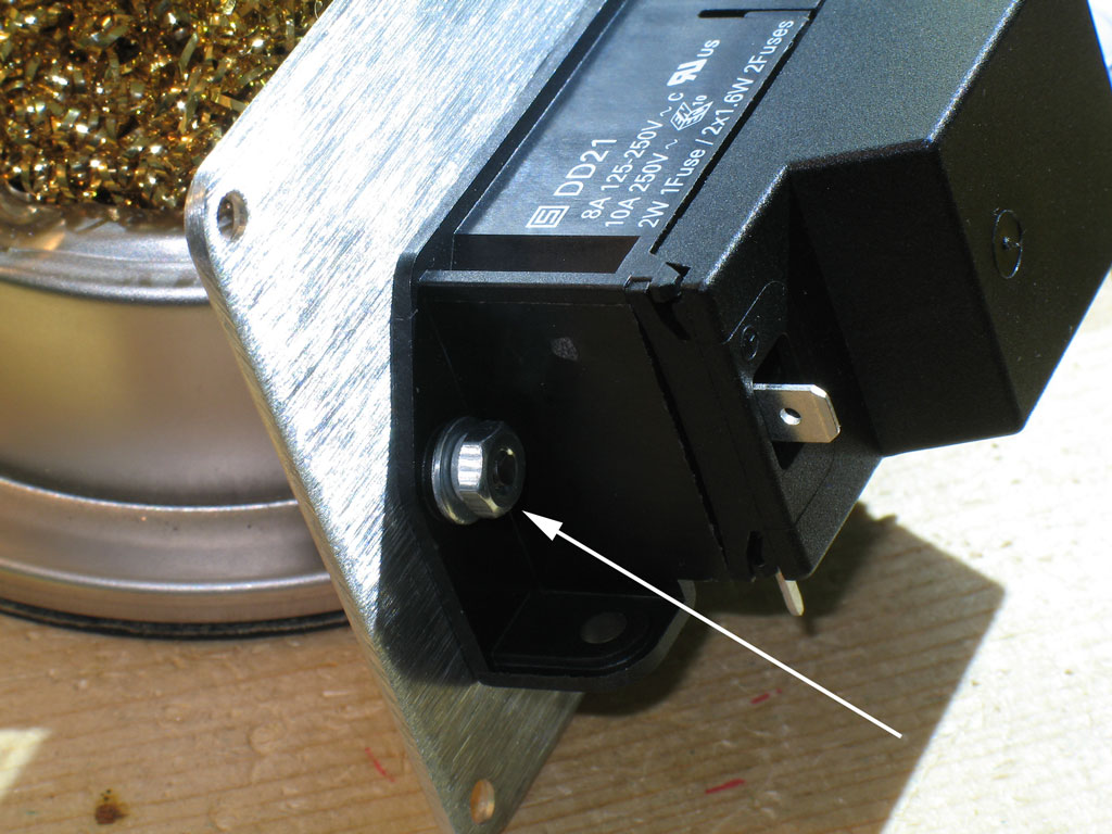
Once you get the standoffs installed on the PCB, slide the PCB assembly into the bottom of the case.  Note that we're in the 2nd slot from bottom (not counting the end plate mounting holes slots).  Slide the PCB in until the back plate (still attached to the PCB) is against the case body.  Don't screw the back plate in at this point, though.  You should screw in the safety ground, first.  That way, you can shift the PCB back and forth as needed until you get the safety ground installed.  I used a 3/8" 4-40 cap screw with a washer and lock washer on the inside.  It's threaded through the safety ground lug and through the hole in the bottom of the case.  On the outside bottom of the case, finish off the screw with a flat washer and nut.
 
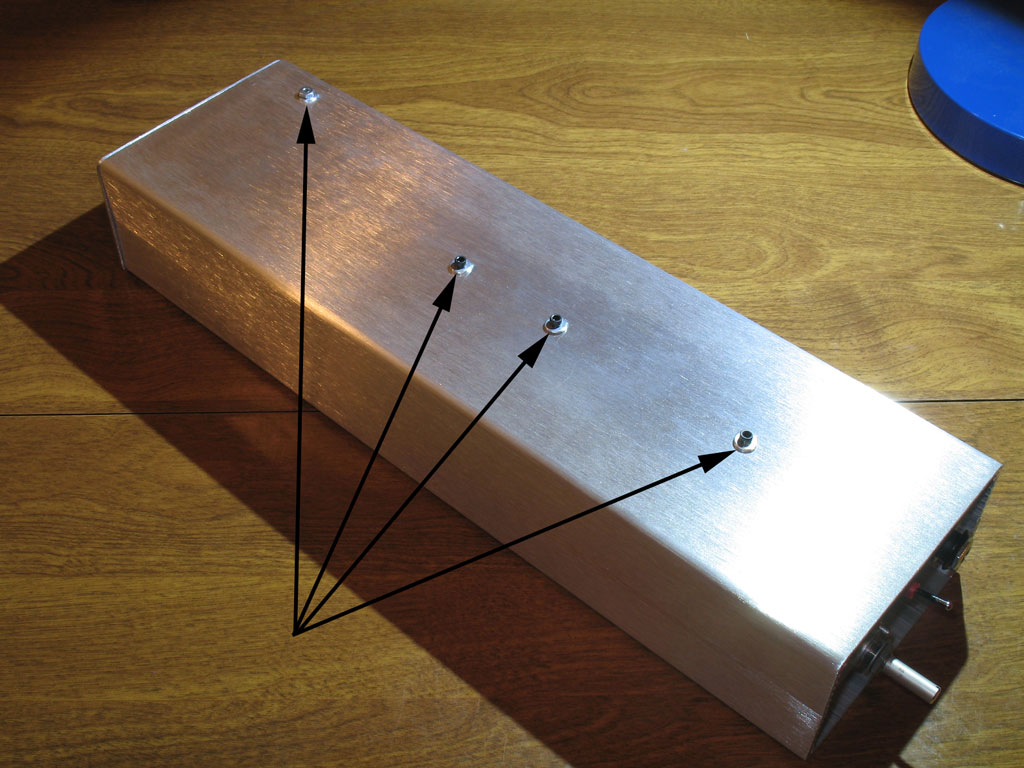
Once you have the safety ground securely attached to the bottom of the case, install the screws into the standoffs and the back plate.  Here we see the case bottom with all of the screws in place (and the two bottom screws of the back plate attached):

 
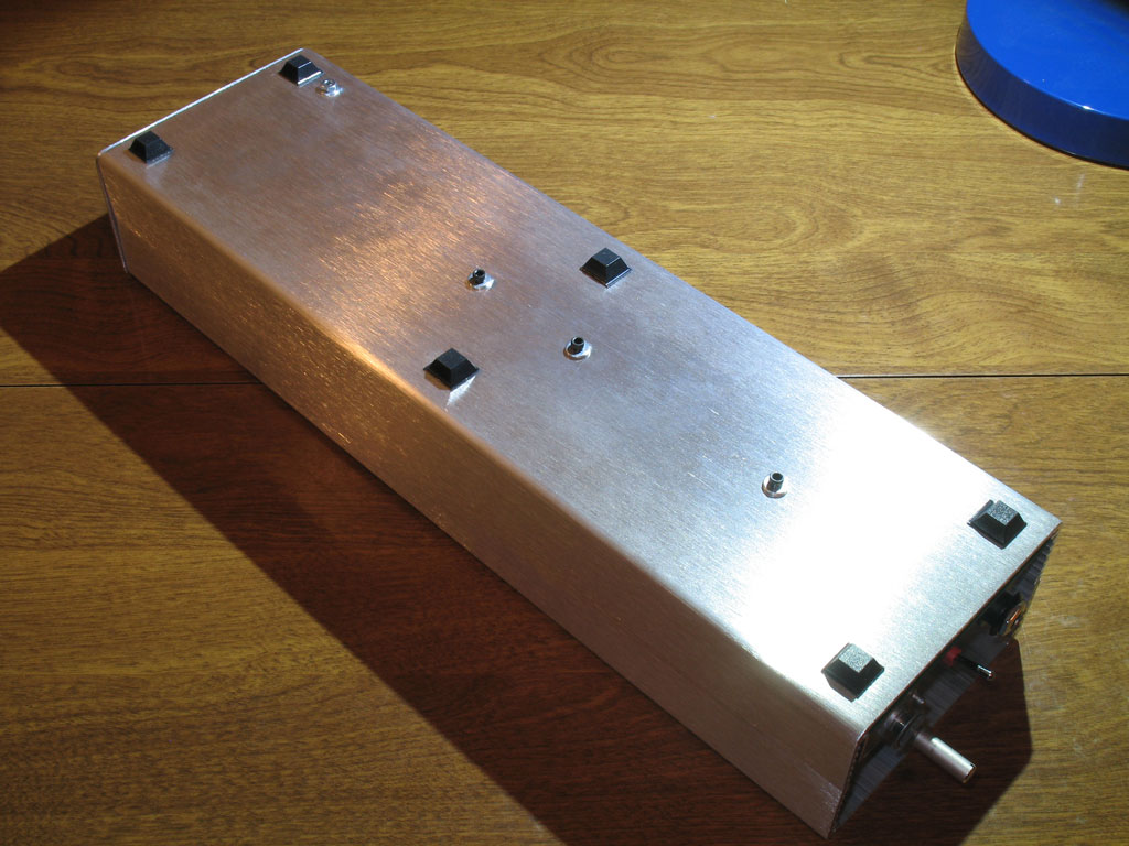
Next the amp doesn't sit so well on those standoff screws and safety ground nut, so I installed the rubber feet.  Because the case is so long, I used six instead of four - it just felt right:

 
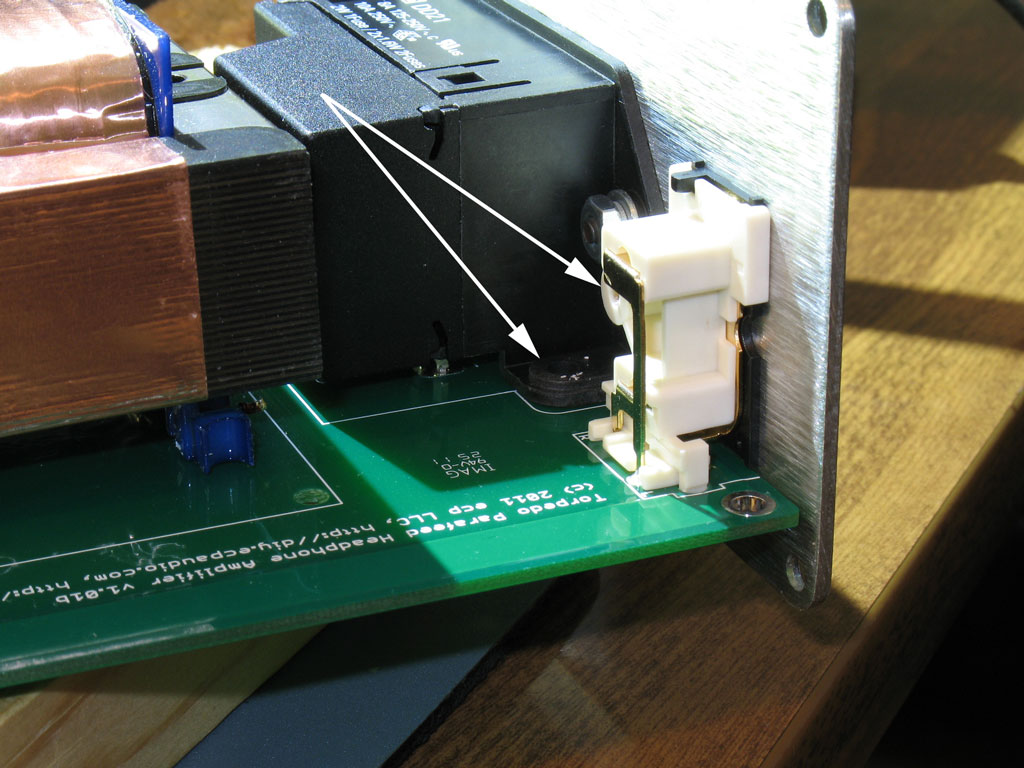
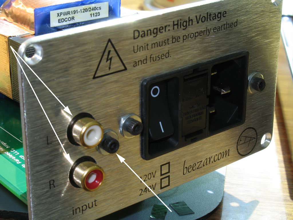
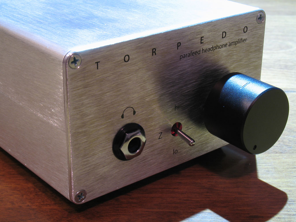
Last, install the front plate by lining up the plate holes with the pot shaft and the headphone jack.  Be certain that the headphone jack tube fits into the end plate hole and be sure the pot locating pin is also positioned correctly.  Finger-tighten the the nuts to both.  Install the bottom two screws of the front plate and go back and tighten down the headphone jack nut and the pot nut.  Finally, install the tubes (don't forget those), place the case lid on top, being careful to seat the top properly into the case bottom's mating-up slots.  Install the top screws for both end plates.  Install the volume knob.  (You may want to trim the shaft - more on that later.)  Here we see the front plate finished and installed:

 
And we're finished building the Torpedo!!


Sep 10, 2011 at 1:36 PM Post #25 of 854


Quote:
This is starting to look better and better. 
beerchug.gif

 
any estimate on the price of the kits? I asume beezar will be selling these as well.

Can't tell you at this point about price, but the answer to other question is sort of assumed.
wink.gif


Sep 16, 2011 at 1:41 AM Post #27 of 854


Quote:
Ready to make an order whenever the kit is up on Beezar, Tom
smily_headphones1.gif


Appreciate that, but Dsavitsk and I are working on an issue that came up with the amp.  I'm sure we'll have a solution shortly.


Users who are viewing this thread

Back
Top