


fishski13
Member of the Trade: SolderWorksAudio
- Joined
- Nov 2, 2004
- Posts
- 1,908
- Likes
- 40
no worries. this is prototyping and a gift to the DIY community.
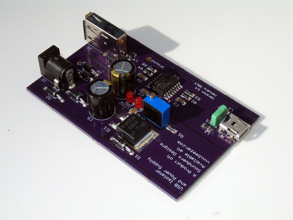
i just need the USB jack. i ordered everything from Digikey this afternoon.
i just need the USB jack. i ordered everything from Digikey this afternoon.


