


marios_mar
Headphoneus Supremus
- Joined
- Jul 21, 2003
- Posts
- 2,381
- Likes
- 18
The idea can be applied to various little DIY amp kits from ebay or your own home built kits.
http://www.ebay.com/itm/DIY-Kit-RA1-Headphone-Amplifier-Kit-Power-AMP-Kit-For-DIY-/150942801493?pt=US_Amplifier_Parts_Components&hash=item2324e45e55
This is the one I bought in particular. It sounds good with my RS-1 and I decided to make a wooden enclosure for it to match the wooden appearance of the RS-1s.
Hope this tutorial - documentation of the process of making it will help some people get ideas on how to pursue a similar project.
I try to mention the techniques used in order to make this amp and affordable tools that many people can acquire.
Please excuse the bad quality of the phone camera pictures. The final project will be photographed with a good camera and technique.
STEP BY STEP TUTORIAL:

This is the pcb before I populated it.

This is the amp right after it was assembled.

It was tested and sounds pretty good.

A spare plank of old wood (chestnut) was used as the base material.

The board was cut in several pieces to select the best pieces of wood appearance wise.

The old finish was stripped off using an electrical wood planer. A manual planer could have also been used.

Here are the resulting pieces of wood.

The pieces were marked using a pencil at approx. 14-15cm length and the width of the wood was kept as it was (approx 12cm)

A circular saw was used to cut the pieces into their proper size. A jigsaw or a manual saw could have also been used instead of the circular saw.

The first cut piece was used as a guide to cut the other one in the same length.

The resulting two pieces that will be stacked on each other to make a tall enough black of wood.

One of the pieces was marked to fit the board and the batteries. This technique that follows was used in order to avoid the use of a router that most people don't have as well as the lack of a thick piece of wood to work with.

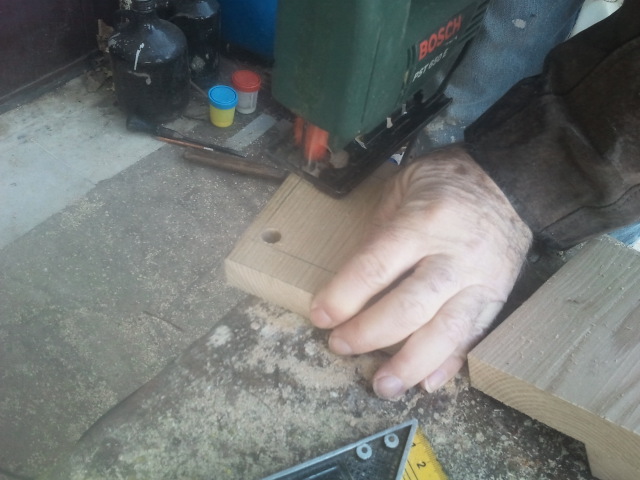
All 4 corners of the markings were drilled with a 1cm diameter drill bit. A normal drill instead of a table drill can also be used of course.

A jigsaw was used to remove the marked part of the wood.

The result.

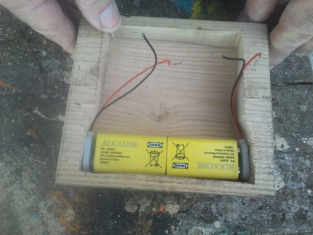
It turned out that we had to widen on one side to fit the two 9V batteries.

Finishing of the widened spot was done with a wood rasp.

Here are the batteries inside the enclosure.

This is the assembled pcb placed on the piece of the top plank to mark the position of the pot and headphone+ jack.

Chisel work was done to make the top plank fit the pot and jack properly so that the shaft comes out in the middle when top and bottom pieces are glued together.

The two planks on top of each other.

Wood glue (white) was spread on the bottom plank.

The two pieces were carefully aligned and pressed onto each other.

The two pieces of plank were pressed with wood clamps until the next day when the glue dried.

Here is the result.

A belt sander was used, 80 grit first and then 120 followed by 220 grit manually. The whole sanding process could have been done completely manually.

A sanding block was used (120 grit) to smoothen the edges of the block.

Care was taken to keep it at 45 degrees angle.

The final marking of the exact position of the pot shaft and headphone jack as well as the RCA jacks on the back and on/off switch etc.

A sharp tool was used to mark the position of the holes.

The diameter of the shaft and headphone jack was measured with a caliper.

A drill bit of a 1mm larger diameter than the measurements was used.

The first step of the finishing process was to stain the wood with a water soluble stain in mahogany color. Approx. 5 grams of solid mahogany stain in a liter of warm water.

Several applications were applied until the wood would not absorb any more stain.

The bottom cover was marked and made out of the casing of a non-working computer PSU. It was cut in rectangular shape with an angle grinder equipped with a thin metal cut-off disc. A jigsaw with a metal cutting blade could also be used or simply metal cutting shears, or a hacksaw. The dimensions it was cut in was approx 2-3 mm smaller than the bottom of the block of the amp.
The edges were smoothened using a file. And 4 holes were made on the corners.

Here is the bottom cover that was just made.
So far the project has taken 5 hours total, and it needed an overnight drying period for the glue.
http://www.ebay.com/itm/DIY-Kit-RA1-Headphone-Amplifier-Kit-Power-AMP-Kit-For-DIY-/150942801493?pt=US_Amplifier_Parts_Components&hash=item2324e45e55
This is the one I bought in particular. It sounds good with my RS-1 and I decided to make a wooden enclosure for it to match the wooden appearance of the RS-1s.
Hope this tutorial - documentation of the process of making it will help some people get ideas on how to pursue a similar project.
I try to mention the techniques used in order to make this amp and affordable tools that many people can acquire.
Please excuse the bad quality of the phone camera pictures. The final project will be photographed with a good camera and technique.
STEP BY STEP TUTORIAL:
This is the pcb before I populated it.
This is the amp right after it was assembled.
It was tested and sounds pretty good.
A spare plank of old wood (chestnut) was used as the base material.
The board was cut in several pieces to select the best pieces of wood appearance wise.
The old finish was stripped off using an electrical wood planer. A manual planer could have also been used.
Here are the resulting pieces of wood.
The pieces were marked using a pencil at approx. 14-15cm length and the width of the wood was kept as it was (approx 12cm)
A circular saw was used to cut the pieces into their proper size. A jigsaw or a manual saw could have also been used instead of the circular saw.
The first cut piece was used as a guide to cut the other one in the same length.
The resulting two pieces that will be stacked on each other to make a tall enough black of wood.
One of the pieces was marked to fit the board and the batteries. This technique that follows was used in order to avoid the use of a router that most people don't have as well as the lack of a thick piece of wood to work with.
All 4 corners of the markings were drilled with a 1cm diameter drill bit. A normal drill instead of a table drill can also be used of course.
A jigsaw was used to remove the marked part of the wood.
The result.
It turned out that we had to widen on one side to fit the two 9V batteries.
Finishing of the widened spot was done with a wood rasp.
Here are the batteries inside the enclosure.
This is the assembled pcb placed on the piece of the top plank to mark the position of the pot and headphone+ jack.
Chisel work was done to make the top plank fit the pot and jack properly so that the shaft comes out in the middle when top and bottom pieces are glued together.
The two planks on top of each other.
Wood glue (white) was spread on the bottom plank.
The two pieces were carefully aligned and pressed onto each other.
The two pieces of plank were pressed with wood clamps until the next day when the glue dried.
Here is the result.
A belt sander was used, 80 grit first and then 120 followed by 220 grit manually. The whole sanding process could have been done completely manually.
A sanding block was used (120 grit) to smoothen the edges of the block.
Care was taken to keep it at 45 degrees angle.
The final marking of the exact position of the pot shaft and headphone jack as well as the RCA jacks on the back and on/off switch etc.
A sharp tool was used to mark the position of the holes.
The diameter of the shaft and headphone jack was measured with a caliper.
A drill bit of a 1mm larger diameter than the measurements was used.
The first step of the finishing process was to stain the wood with a water soluble stain in mahogany color. Approx. 5 grams of solid mahogany stain in a liter of warm water.
Several applications were applied until the wood would not absorb any more stain.
The bottom cover was marked and made out of the casing of a non-working computer PSU. It was cut in rectangular shape with an angle grinder equipped with a thin metal cut-off disc. A jigsaw with a metal cutting blade could also be used or simply metal cutting shears, or a hacksaw. The dimensions it was cut in was approx 2-3 mm smaller than the bottom of the block of the amp.
The edges were smoothened using a file. And 4 holes were made on the corners.
Here is the bottom cover that was just made.
So far the project has taken 5 hours total, and it needed an overnight drying period for the glue.
")
