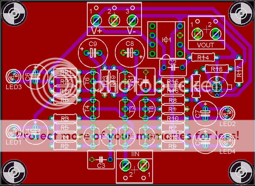
Discrete I/V converter design

Apr 11, 2007 at 10:17 PM Post #16 of 33
Quote:

Originally Posted by AndrewFischer /img/forum/go_quote.gif
Yeah the specs are darn good. I've got a few DVDs with Linear PCM 2-channel audio.
I'm not sure if any of them are 24-bit. My receiver tells me the sampling rate but not the bits per sample.

In any case I doubt I'll use a AD1862 for my next DAC since as you pointed out they are hard to find.

Digikey has the PCM1704K for a mere $30, but it is not recommended for new designs. <sigh>


Yeah, I got lucky when buying mine, and would have gotten more than just the four had I had the funds for it. If your receiver is telling you the sample rate, I suspect that it is a video DVD, and the audio is just 48/16, because, AFAIK, not many devices support sending high resolution audio over the digital outs.

If I wasnt able to get these DACs, I definitely would have chosen the PCM1704. No reason for you not to grab them while they are still being produced and available from places like Digikey. I suspect strongly that the prices for these will go up drastically once TI finally stops making them, as they have a pretty strong following. I dont really feel any of the new DACs are superior, especially as most (all?) of them are delta sigma designs.

Quote:

Originally Posted by regal /img/forum/go_quote.gif
I actually have a AD1862 DAC made by AA that I have been trying to find a discrete I/V+filter to replace the OPA275's. It has the PMD-100 with the -6db done in that analog domain at the low-pass filter after I/V so it makes it a little tricky to find a drop-in solution.

Cetoole I have the complete schematics for this DAC if you are interested I can email them to you.


I would prefer you send me that PMD-100, though I have a pair of SM5847 digital filters on the way which should be pretty good. Cant get my hands on a PMD-100 (seen a few sell for $150 recently, no way I am paying that much, thats around double what I paid for my DACs, and I got four of them)Gotta come up with some glue logic though so it can accept the I²S output of a PCM2707. I will take a look at how to implement that -6dB analog attenuation the PMD-100 requires due to how HDCD works, but why do you really need it? I can see the volume discrepancy on some discs bothering consumers, but its not like all CDs are normalized anyways, and I am sure you have another attenuator of some sort elsewhere in your system, so it isnt like you will be unable to get the volume right. YGPM.
 
Apr 12, 2007 at 12:40 AM Post #17 of 33
Did some searching and thinging about how to impliment this output level scaling. I really dont like the idea of attenuating the signal, so we will stick with amplifying, though it would be easy to do either. The PMD-100 datasheet shows a simple circuit in which a transistor drives a relay, which connects a resistor connected to the inverting input of the buffer opamp to ground, increasing the gain from unity to, I assume, 2. The output buffer shown here is unity gain open loop, unlike an opamp in which the gain can be increased, so you could change the buffer to an opamp and control the gain in this mannor. We have an additional option when using this discrete circuit, and this is probably how I would impliment it.

In this circuit, output voltage is a function of two things, current output of the DAC and the value of R1. R1 functions exactly the same way as a passive I/V converter, which is just a resistor on the output of the DAC to ground. Instead of using just one resistor for R1, use two in series, and have a relay, the Omron G5V-1-DC5 would be a good choice, short one of them out, so that when pin 5 is low, the relay shorts the second resistor, so choose the value of the first resistor to give 2v output. When pin 5 goes high, the relay powers, and the two resistors are in series. Since you want the high output signal to be 4v, have both resistors be equal in value. The signal either goes through a resistor and the unpowered relay (low) or two resistors in series.

This probably doesnt read very clearly, so I will draw it up in Eagle when I get home tonight from Comp Sci class (about an hour).
 
Apr 12, 2007 at 1:02 AM Post #18 of 33
Quote:

Originally Posted by cetoole /img/forum/go_quote.gif
If your receiver is telling you the sample rate, I suspect that it is a video DVD, and the audio is just 48/16, because, AFAIK, not many devices support sending high resolution audio over the digital outs.


Now that I'm home, I went and took a look. I was surprised to find it is 48Khz/24bps with DTS 5.1 as the only other audio track.

I apologize for the thread jack. If anyone wants to discuss this lets do it here:

http://www.head-fi.org/forums/showth...42#post2867442

=================================
 
Apr 14, 2007 at 6:55 PM Post #21 of 33
cetoole,

I think I may try to build this instead of shilling out $225 for a Zapfilter. It looks simple enough to do an a breadboard. Do you have a BOM ?
 
Apr 17, 2007 at 1:31 PM Post #22 of 33
Quote:

Originally Posted by regal /img/forum/go_quote.gif
cetoole,

I think I may try to build this instead of shilling out $225 for a Zapfilter. It looks simple enough to do an a breadboard. Do you have a BOM ?


I do not have a BOM, but parts selection should be pretty simple. Choose resistor values in the CCSs to run T1 and T3 both at ~10mA. You will probably want to make the T5 and T7 CCSs adjustable. Since a current mirror isnt perfect, you will want to adjust the T5 CCS to compensate, and because of the input current from the DAC, you will want to be able to configure it during setup, with the servo opamp removed, to get it as balanced as possible. I am not sure how to calculate the ideal value for the base bias of T3, but ~10v should work pretty good. Choose R1 to get your desired output voltage, using Ohm's law, with I being the current output of your DAC. C1 is for a lowpass filter, choose it so as not to affect the audio frequencies significiantly, but filter a lot of that HF crud out. You may want to make this a 2nd order or even 3rd order filter. Look at the Gilmore DynaXX amps for ideas about servo component values, and I think Borberly shows some component values which could be used for the FET buffer. I dont remember the resistances that are ideal offhand, and have to run.
 
May 4, 2007 at 3:25 AM Post #24 of 33
Quote:

Originally Posted by Pars /img/forum/go_quote.gif
Have you done anymore with this design yet? It looks interesting for my Rotel...

Chris


Pars, it depends what you mean by "done anymore with this design". I havnt changed the schematic or layout, but I have started choosing some initial parts values. Some values are dependent on the DAC you will be using it with, due to output current from the DAC, and voltage it needs to see on its output. Also you have to determine what output voltage you want from the I/V converter.
 
May 4, 2007 at 4:42 AM Post #25 of 33
Quote:

Originally Posted by cetoole /img/forum/go_quote.gif
Pars, it depends what you mean by "done anymore with this design". I havnt changed the schematic or layout, but I have started choosing some initial parts values. Some values are dependent on the DAC you will be using it with, due to output current from the DAC, and voltage it needs to see on its output. Also you have to determine what output voltage you want from the I/V converter.


I guess I meant built one and tried it. I would be using this with a TDA1541A, so 4mA current, with probably 1.3-1.5K for R1. I have been looking at the different Jocko flavors, and at rbroer's "less simple" variant over on diyaudio, which I like because it doesn't use coupling caps (same with yours). BTW (you may have posted this) but what is the board size on these?

Chris
 
May 4, 2007 at 6:44 AM Post #26 of 33
Quote:

Originally Posted by Pars /img/forum/go_quote.gif
I guess I meant built one and tried it. I would be using this with a TDA1541A, so 4mA current, with probably 1.3-1.5K for R1. I have been looking at the different Jocko flavors, and at rbroer's "less simple" variant over on diyaudio, which I like because it doesn't use coupling caps (same with yours). BTW (you may have posted this) but what is the board size on these?

Chris


No, I havnt built one. This is really something I am working on for a complete DAC design. I dont have any sources to mod with this.

As for the size...
Quote:

Originally Posted by cetoole
It currently measures 69.85x50.80mm, or 2.75x2", and this is only a single channel. Bit bigger than just an opamp, eh?


Now, if you are able to etch a 2 sided board, and move some parts to smd, then you can make it a good bit smaller. I am not planning on having any of these made alone, but I will get a multiproject panel made up at some point.
 
May 4, 2007 at 3:09 PM Post #27 of 33
Thanks. I currently have rbroer's more complicated design laid out on 3.7" x 2.7" for a single channel. I tried emailing him, but no reply yet, just to get his thoughts, as this is a 3-4 year old design. 2.75" x 2" sounds better, and I like the fact that yours does use a current mirror. Would you be willing to share the Eagle files for his?

Chris
 
May 5, 2007 at 2:26 AM Post #28 of 33
Some questions, from an unlearned guy (me):

Would this work with a PCM-1796 current out DAC?

Now if the DAC chips are run in dual-mono for each channel (i.e. one 2ch DAC chip per channel) do you just run both V+ ouputs from each side of the DAC to Input 1, and both V- outputs to Input 3?

Would the output be 2.0 vrms (standard CD unbalanced output voltage), or do you need some amplification/buffer stage for the output?
 
May 5, 2007 at 5:41 AM Post #29 of 33
Quote:

Originally Posted by DigiPete /img/forum/go_quote.gif
Some questions, from an unlearned guy (me):

Would this work with a PCM-1796 current out DAC?

Now if the DAC chips are run in dual-mono for each channel (i.e. one 2ch DAC chip per channel) do you just run both V+ ouputs from each side of the DAC to Input 1, and both V- outputs to Input 3?

Would the output be 2.0 vrms (standard CD unbalanced output voltage), or do you need some amplification/buffer stage for the output?


Why PCM1796, instead of PCM1792A? You can use this I/V with that DAC though. I would have to study the datasheet more to see how mono mode works though. Do you have two + and two - outputs per DAC, and do I/V conversion on each? If so, you can do that with this circuit.

Output voltage depends on DAC output current, and the value of R1. Use Ohm's law to figure out the output voltage based on these two factors.
 
May 5, 2007 at 1:40 PM Post #30 of 33
My Denon 3930CI Universal player has the 1796 Dacs.

"Do you have two + and two - outputs per DAC, and do I/V conversion on each?"

Each DAC has two V+(r,l) and two V-(r, l).

Here is what a friend sent me about my player from a picture he saw of the audio board:

The stereo DACs each run one channel, and
> the outputs are paralleled. The important question is whether the
> outputs are summed before or after the I-V opamps. From the picture,
> it looks like they run separate I-V opamps then sum the voltage
> signals from those opamps. I need to get a schematic to be sure, and
> I'm going to look into getting one soon. If this is the case, I might
> have to look into whether the current outputs can be paralleled directly or not.

I was thinking about how to use your circuit instead of a Zapfilter, and get balanced outputs.

denon_dvd_3930_inside.jpg
 

Users who are viewing this thread

Back
Top