Decision made... Building a CMoy
Mar 22, 2007 at 4:26 AM Post #31 of 52
Well I have a handful of 5mm led bevel things that snap into a hole and hold the led in place. Haven't even used them yet.

I personally use hot melt glue as it holds them in well, insulates etc. but it's quite often fairly easy to just peel or rip off if you want to remove the LED. Worst case scenario you could use a heat gun or soldering iron to melt it if you couldn't get it off, although never had that happen before.
 
Mar 30, 2007 at 11:11 PM Post #32 of 52
All of my parts had arrived and were sitting in front of me, waiting to be assembled. I began putting some jumpers (resistor lead cuttings) in the PCB, and when I had put two in, I decided to test my soldering skills.

My soldering iron's tip won't melt solder.
redface.gif
It's a Radio Shack 30-watt iron, so go figure.

I tried cleaning the oxidation off of the tip by tinning it, but the solder just dribbled off, not at all like in tangent's video. I'm assuming I need a new soldering tip as this one looks pretty black (even though I've only used it twice before for quick soldering jobs), but I'm more eager to just scrap this one.

I shouldn't have to wait 15 seconds and/or use pressure to melt solder, correct?
blink.gif


I've read a lot of soldering iron suggestions, but figured I'd ask about one with a specific purpose in mind: building this CMoy. That means I'd prefer a small tip on the new iron. Any suggestions in the $0-$30 range?
 
Mar 31, 2007 at 1:32 AM Post #33 of 52
Like I said in the video, just canvas your local stores to see if you can find something more geared to electronics. There is no trickery in the video, so don't second-guess what you see: you should see the same thing if you're using a good iron and an appropriate solder type.
 
Mar 31, 2007 at 2:03 AM Post #34 of 52
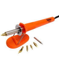
I noticed that colonelkernel8 mentioned Weller irons on the first page... It looks like Lowe's carries a Weller 25-watt iron:

http://www.lowes.com/lowes/lkn?actio...5HK&lpage=none
037103200655md.jpg


This is supposedly for wood burning, but it looks like it has a fair amount of useful tips. I realize that Lowe's qualifies as a home improvement store, but I'm in a fairly rural area right now and there aren't many small electronics shops.

Tangent, what kind of iron do you use in your tutorial? I think the small chisel tip would probably be more useful than a conical tip, as you suggest in the Getting Started section.
 
Mar 31, 2007 at 2:29 AM Post #35 of 52
Quote:

Originally Posted by infinitesymphony /img/forum/go_quote.gif
This is supposedly for wood burning, but it looks like it has a fair amount of useful tips.


If you can find a reasonably small tip, then yes, that's probably a good choice. I would tend to avoid Lowes or anything like it, just because they probably won't carry a reasonable selection of tips. Even if they do now, will they next year when you need a replacement?

Quote:

I'm in a fairly rural area right now and there aren't many small electronics shops.


I doubt many here are more rural than I am. The "big city" nearby has only 40,000 people. The entire county has less than 100,000. The nearest thing anyone would rightly call a real city is 3 hours' drive away. If I can find a decent iron locally, I'll bet you can, too.

Quote:

what kind of iron do you use in your tutorial?


I purposefully didn't say because it's a no-name iron. The chance that you can find one just like it is essentially zero. What matters is that you now know how to recognize a reasonable iron when you see it.
 
Mar 31, 2007 at 7:05 AM Post #36 of 52
I scraped off all of the oxidation using some coarse sandpaper, and after waiting a while longer for the iron to warm up, it was hot enough to solder. It's not exactly soldering well, but it works!

I've been putting together the amp for the past five or six hours, since this is my first build and I'm taking my time. The power test worked perfectly.

Now I'm at the part where the two power wires (V+ and V-) are soldered to the IC socket on the back of the board. What's the best way to hold the wire still?

This seems like it potentially could be the most annoying part of the build, since one false move threatens to ruin other close solder joints.
 
Mar 31, 2007 at 7:54 AM Post #37 of 52
Sounds like you should still go and fine a better iron. If it is not heating properly you will get cold solder joints. You can also damage components if you need to heat them for more than a few seconds to get the solder to flow.

It is easier to put the wires on the top of the board and stick them through just like the other parts. Then the holes hold them in place. You can use one of the single pads and bend the wire to contact the pins.
 
Mar 31, 2007 at 6:29 PM Post #39 of 52
Here's what it looks like so far...

cmoy1.jpg


Quick question about my 1/8" (3.5mm) stereo connectors:

cmoy2.jpg


There are four pins on the bottom and one near the jack itself. What is each pin's function? Do the bend directions indicate which pins are related?
 
Mar 31, 2007 at 6:30 PM Post #40 of 52
Quote:

Originally Posted by infinitesymphony /img/forum/go_quote.gif
Do most people add those wires on the top instead of the bottom?


I'd imagine they do it on the bottom as the wires may interfere with components on the top, you can look at doing that of course, depends a lot on how you've laid it out and what sort of components you're using as to if it's an issue.
 
Mar 31, 2007 at 8:19 PM Post #41 of 52
Quote:

Originally Posted by infinitesymphony /img/forum/go_quote.gif
There are four pins on the bottom and one near the jack itself. What is each pin's function? Do the bend directions indicate which pins are related?


Check datasheet first. it will tell you what goes where.
It looks like the upper 1 pin is the ground, two pins at the bottom is left and right. those two pins are connected to each other, and act like a switch when plug is inserted. You may not need this switch function, so solder them both, connect your left or right on it. And, again, check data sheet first to see what really goes where.

Quote:

Originally Posted by infinitesymphony /img/forum/go_quote.gif
Do most people add those wires on the top instead of the bottom?


Doesn't matter as long as there's a space. Do the way you prefer.
 
Mar 31, 2007 at 8:39 PM Post #42 of 52
There were no datasheets included with the jacks, and there's also no relevant information about them on Digikey's page (part no. CP-3545-ND).

It seems like I remember reading or hearing something about using a multimeter to figure out what each pin does... I guess that would only tell me which pins are connected somehow.
 
Mar 31, 2007 at 9:08 PM Post #44 of 52
Oh, cool... Thanks Seaside! That saves me a lot of worry.

How did you find the datasheet? I'm a Digikey n00b. And yes, that's the exact part with the manufacturer's part number (SJ-3545).

Is this correct?

cmoy2_commented.jpg
 
Mar 31, 2007 at 11:56 PM Post #45 of 52
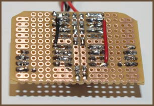
Well... I just attempted to put the black wire on the back of the board for the third time and, when I failed, the bottom copper pad (first op-amp pad) tore off. Can I just create a solder bridge to connect the wire to the op-amp?

I'm finding this part of the build nearly impossible... I've already created a bunch of solder bridges by accident just trying to solder in the wire, and the wire seems like it has to be an exact length (down to the micrometer) in order to avoid shorting it on one of the other connections. Holding it in place has also become an issue--because the top joint is already filled with solder from one of the jumpers, I can't put it through the hole to stabilize it.
 

Users who are viewing this thread

Back
Top